


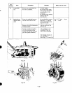
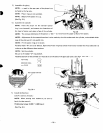
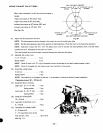
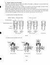

INTAKE, EXHAUST VALVE TIMING
When valve clearance
is
at
0.4
mm
and the engine
is
heated,
intake valve opens at
16O
before TDC,
intake valve closes
at
54'
after BDC,
exhaust valve
opens
at
54'
before BDC, and
exhuast valve closes at
14"
after TDC.
(See
Fig.
50.)
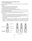
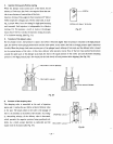
Adjust the decompression clearance.
TDC
(TOP
DEAD CENTER)
INTAKE VALV
INTAKE VALV AUST
VALVE
BDC
(BOTTOM
DEAD CENTER)
Fig.
50
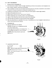
NOTE:
The
decompression device locates
in
the rocker arm
on
the intake valve side.
NOTE:
Set
the
decompression lever at
the
position
of
decompression. (Push the lever
to
the
horizontal position.)
NOTE:
Clearance
is
about
0.5
mm.
Turn
the adjust screw
until
it
touches the decompression shaft, and then make
another half
turn.
Threading
of
this
screw
is
1
.O
mm.
Turn
the flywheel
by
hand and check a contact between the valve and the
piston.
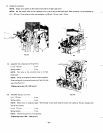
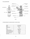
Assemble the rocker cover.
6
x35
7Tbolt.
...........
3pcs.
Spring washer
............
3
pcs.
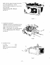
NOTE:
Check
if
there
is
an
"0"
ring
for
breather hole
on
the surface
of
the head (intake breather's side).
NOTE:
Check
if
the gasket
for
the
rocker cover
is
put
correctly
in
the groove.
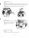
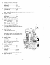
Install the nozzle holder.
6
mm
nut
...............
2
pcs.
Spring washer
............
2
pcs.
NOTE:
Pay attention
to
the gasket at the top.
It
is
advisable
to
utilize the driver foreasy installation.
[Tightening torque:
90
-
100
kg-cml
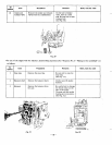
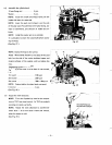
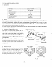
Install the blower housing.
Upper part:
8
x
55
7T
bolt
...
2
pcs.
Spring washer
....
2
pcs.
Lower part:
8
x
40
7T
bolt
...
2
pcs.
Spring washer
....
2
pcs.
10
x
30
bolt
.............
4
pcs.
8
x
16 bolt
..............
4
pcs.
6
x
8
flange bolt
...........
2
pcs.
bolt and nut
5
mm
.........
1
pce. each
Install the
driving
shaft.
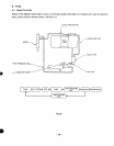
Assemble the flywheel cover.
Assemble the cylinder baffle.
5
x
75
round head cross recess
(See
Fig.
5
1
.)
Fig.
51
26
-