


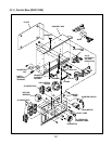


53
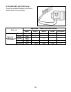
2
4
(AC output)
(
AVR
)
1
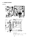
CONTROL BOX
Fuel cut
Ignition coil
Auto choke
(
Bimetal
)
Electric
starter
Oil pressure
switch
Regulator
Magnetic
switch
Charge
coil
Exciting
coil
-
+
Battery 12V
Grn/Y
Grn
LBlu
Gry W
Key
switch
to earth
terminal
ST Relay
Connector
(
Remote control
)
Gry
R15
Blk15
Grn
WW
W
Blk/W
Gry
Gry
Blk
R
Blk/W
Blk
R
Grn/Y
Grn/Y
Grn
Grn
Org
R
Org
Org
LBlu
LBlu
LBlu
Brn
Y
Org
R
W
W
W
W
W
W
W
OFF
-
M+MB
L
.
IG
ST
ON
START
R/W
Idle
solenoid
1
Electronic control unit
2
13
3
12
4
11
5
10
6
987
Blk
Y
Y
Blk
Grn/Y
Grn/Y
Idle control
switch
Idle
control
unit
Oil pressure
warning lamp
(
Red
)
LGrn
Org
Blk
Blu
Blk
R
R
Blk
W W
W
LGrn
Grn/Y
Grn/Y
Grn/Y
Grn/Y
Brm
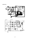
CONTROL BOXGENERATOR
No-fuse breaker
Voltmeter
Hour meter
Pilot lamp
VHr
PL
Earth(Ground)
terminal
Brush
Auxiliary
Winding
Field
Winding
AC WindingAC Winding
AVR
Exciting coil
(Engine)
Idle
control
unit
AC otuput
receptacle(120V)
AC output
receptacle(120V)
AC output
receptacle(120/240V)
AC output
receptacle(120/240V)
YY
REC1 REC2
REC3
REC4
REC5
WW
WW
XX
YY
HH
G
GG
GG
Key switch -M
Idle control unit 3
Blk
Y
Y
W
W
LGrn
Brm
46
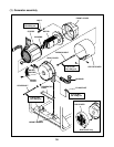
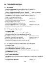
Wiring color cord
LGrn
R/W
Blk/RBlk Black Brn/W Brown/White R Red
Blk/W Black/White Grn Green W White
Blu Blue Grn/W Green/White Y Yellow
LBlu Light blue Org Orange Pik Pink
Brn Brown Gry Gray Grn/Y Green/Yellow
Light green
Red/White
Black/Red
11. WIRING DIAGRAM
(RGV12100)