


35
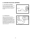
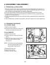
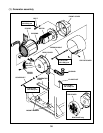
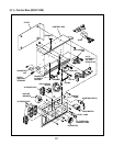
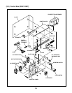
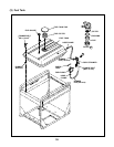
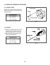
9-3 COMPONENT PARTS
For disassembling and assembling, the following illustrations show the major component parts
and their configuration for (1) Generator assembly, (2) Control Box and (3) Fuel Tank and sys-
tem.
The specified tightening torque is indicated in the illustration.
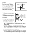
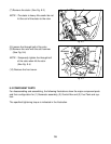
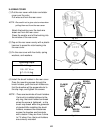
(8) Loosen the through bolt of the rotor.
(9) Remove the rotor with the soft hammer.
(See Fig. 9-4)
NOTE : Temporarily tighten the through bolt
of the rotor when hit the rotor.
(See Fig. 9-4)
(10) Remove the front cover.
ROTOR
SOFT
HAMMER
THROUGH
BOLT
Fig. 9-4
Fig. 9-3
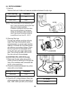
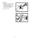
(7) Remove the stator. (See Fig. 9-3)
NOTE : The stator is heavy. Be careful do not
hit the coil of the stator to the rotor.