


TABLE OF FIGURES
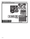
Figure 1: Top and Bottom Panel Label Placement....................2
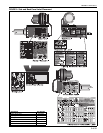
Figure 2: Side and Back Panel Label Placement......................3
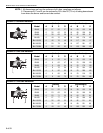
Figure 3: Standard Reflector.....................................................6
Figure 4: One Side Reflector.....................................................6
Figure 5: Two Side Reflectors ...................................................6
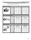
Figure 6: 45° Tilt Reflector ........................................................7
Figure 7: U-Tube, Standard Reflector........................................7
Figure 8: U-Tube, 45°................................................................7
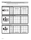
Figure 9: U-Tube, Opposite 45° Reflector .................................8
Figure 10: 2-Foot Deco Grille and Protective Grille ...................8
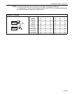
Figure 11: Lower Clearance Shield ...........................................8
Figure 12: Venting.....................................................................9
Figure 13: Major Component Descriptions.............................. 11
Figure 14: Critical Hanger Placement .....................................15
Figure 15: Linear Heater Assembly Overview ........................16
Figure 16: Linear Heater Layout Overview .............................17
Figure 17: Linear Heater Layout Overview (Continued)..........18
Figure 18: U-Tube Heater Assembly O
verview ......................26
Figure 19: U-Tube Heater Layout Overview ...........................27
Figure 20: U-Tube Layout Overview (Continued)....................28
Figure 21: Reflector Joint Detail..............................................30
Figure 22: Tube Termination ...................................................36
Figure 23: Gas Connection with Flexible Gas Hose................42
LIST OF TABLES
Table 1: Contents of BH-Series Burner Carton.......................12
Table 2: Contents of Core and Extension Packages ..............12
Table 3: BH-Series Component Package Guide ....................13