


BH-SERIES INSTALLATION, OPERATION AND SERVICE MANUAL
8 of 59
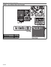
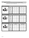
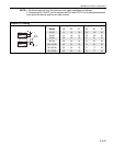
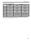
NOTE: 1. All dimensions are from the surfaces of all tubes, couplings and elbows.
2. Clearances B, C and D can be reduced by 50% after 25' (7.5 m) of tubing downstream
from where the burner and burner tube connect.
*When installed in the first 10' (3 m).
FIGURE 9: U-Tube, Opposite 45° Reflector
(inches) (centimeters)
Model ABCDABCD
BH-40
- UNAPPROVED - - UNAPPROVED -
BH-60 8 54 59 22 21 138 150 56
BH-80 8 60 65 22 21 153 166 56
BH-100 10 64 73 22 26 163 186 56
BH-115/125 10 70 77 22 26 178 196 56
BH-140/150 12 74 83 22 31 188 211 56
BH-175/200 12 76 85 22 31 194 216 56
B
A
C
D
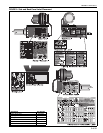
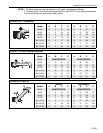
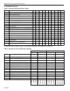
FIGURE 10: 2-Foot Deco Grille and Protective Grille
(inches) (centimeters)
Model ABCDABCD
BH-40 6 27 52 27 16 69 133 69
BH-60 6 35 62 35 16 89 158 89
BH-80 6 38 65 38 16 97 166 97
BH-100 6 40 70 40 16 102 178 102
BH-115/125 6 46 76 46 16 117 194 117
BH-140/150 6 50 79 50 16 127 201 127
BH-175/200 8 52 82 52 21 133 209 133
C
BD
A
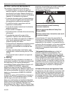
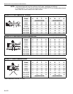
FIGURE 11: Lower Clearance Shield*
(inches) (centimeters)
Model ABCDABCD
BH-40 6 34 27 34 16 87 69 87
BH-60 6 39 33 39 16 100 84 100
BH-80 6 40 38 40 16 102 97 102
BH-100 6 50 44 50 16 127 112 127
BH-115/125 6 54 48 54 16 138 122 138
BH-140/150 6 55 50 55 16 140 127 140
BH-175/200
- UNAPPROVED - - UNAPPROVED -
C
BD
A