


10
ASSEMBLY
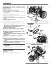
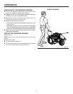
Fig. 6
HANDLE
HANDLE
KNOB
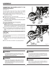
RAISING AND LOWERING HANDLE
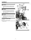
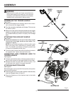
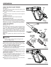
ATTACHING THE WHEEL ASSEMBLY AND
SUPPORT FOOT
See Figures 3 and 4.
Locate the support feet, nuts, and bolts.
Lift the machine and slide the support feet into the
machine base.
Secure in place using the bolts and nuts.
Locate the axle, hitch pins, washer, and wheels. Remove
the hitch pin from the axle.
Slide the axle through the hole in the center of the
wheel.
Slide the washer onto the axle.
Lift the machine and slide the axle into the wheel mount-
ing hole in the machine base as shown.
Push the hitch pin into the hole on the end of the axle to
secure the wheel assembly.
NOTE: The hitch pin should be pushed into the axle until
the center of the pin rests on top of the axle.
Repeat with the second wheel.
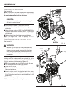
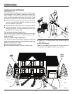
ATTACHING THE TRIGGER HANDLE REST
See Figure 5.
Locate the trigger handle rest (front and back), screws,
flat washer, and lock nut.
Push the screws into the holes. Tighten securely using
the lock nut.
RAISING AND LOWERING THE HANDLE
See Figure 6.
To raise the handle: pull the handle up until the handle
knob snaps through the locking hole to secure the handle
in place.
To lower the handle: pull the handle knob out then lower
the handle to the position shown in figure 6.
CAUTION:
Failure to remove pump oil plug label may result in
decreased pump life.
REMOVE THE LABEL
See Figure 6.
Remove pump oil cap label from the oil pump.
Fig. 5
TRIGGER HANDLE
REST (BACK)
LOCK
NUT
Fig. 4
BOLTS
SUPPORT
FOOT
NUT
FLAT
WASHER
LABEL
SCREW
SCREW