


8 — English
ELECTRICAL
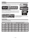
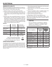
ELECTRIC MOTOR LOADS
It is characteristic of common electric motors in normal operation to draw up to six times their running current while start-
ing. This table may be used to estimate the watts required to start “Code G” electric motors; however, if an electric motor
fails to start or reach running speed, turn off the appliance or tool immediately to avoid equipment damage. Always check
the requirements of the tool or appliance being used compared to the rated output of the generator.
Motor Size (H.P.) Running Watts
Watts Required to Start Motor
Repulsion Induction Capacitor Split Phase
1/8 275 600 850 1200
1/6 275 600 850 2050
1/4 400 850 1050 2400
1/3 450 975 1350 2700
1/2 600 1300 1800 3600
3/4 850 1900 2600 —
1 1100 2500 3300 —
CAUTION:
Operating voltage and frequency requirement of all
electronic equipment should be checked prior to
plugging them into this generator. Damage may result
if the equipment is not designed to operate within a
+/- 10% voltage variation, and +/- 3 hz frequency
variation from the generator name plate ratings.
To avoid damage, always have an additional load
plugged into the generator if solid state equipment
(such as a television set) is used. A power line
conditioner is recommended for some solid state
applications.
EXTENSION CORD
See Figure 1.
The 25-ft. extension cord (Model RDEC25) has a 240 Volt,
20 Amp twist lock plug on one end and a 240 Volt, 20 Amp
twist lock receptacle on the other end. It also has a 12 Volt
DC engine control connector on each end. When using this
cord, the removable control panel can provide power through
the 2 x 120 Volt duplex GFCI outlets on the control box.
CAUTION:
Use only with RDEC25 accessory cord. Do not exceed
separation length of 75 ft. or a combination of three
RDEC25 accessory cords.
GROUND FAULT CIRCUIT INTERRUPTER
See Figure 2.
The 20 amp, 120 volt receptacles on the generator are pro-
tected by a Ground Fault Circuit Interrupter (GFCI), which
guards against the hazards of ground fault currents. An
example of ground fault current is the current that would
flow through a person who is using an appliance with faulty
insulation and, at the same time, is in contact with an electri-
cal ground such as a plumbing fixture, wet floor, or earth.
GFCI receptacles do not protect against short circuits,
overloads, or shocks.
The GFCI receptacles can be tested with the TEST and
RESET buttons.
To test:
Depress the TEST button. This should cause the Reset
button to pop out.
To restore power, depress the RESET button.
Perform this test monthly to ensure proper operation of the
GFCI. If the generator is stored outdoors, unprotected from
the weather, test the GFCI receptacle before each use.