MAINTENANCE
SE4 05/05 Maintenance Section 5-11
© 2005 Alamo Group Inc.
MAINTENANCE
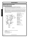
MAIN GEARBOX
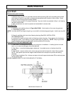
1.Remove bearing (Ref. #8 Figure 8) from inside main housing. A special slide hammer puller
(PROTO No. 4056) or equal may be required to remove bearing. Press in new bearing using driving
tube or pipe with approximate same OD. as bearing. Seat outer race of bearing against shoulder in
housing.
GEARBOX ASSEMBLY STEPS
Clean and scrape all gasket surfaces.
A.
1.Insert output shaft assembly into main housing and press into place. NOTE: Use pipe or tube with
approximate same OD. as bearing and press into place by striking or pressing on tube.
2.Prelube lower bearing.
3.Place lower gasket in place and then carefully slide bearing retainer cap assembly down shaft.
4.Install bolts and lockwashers and torque to 40-50 ft. lbs.
B.
1.Assemble three shims onto input shaft housing. Insert input shaft assembly into main housing by
installing shaft end into bearing in main housing. It may be necessary to rotate shaft to align gear teeth
so that housing will install completely.
2. Install washers and bolts and torque to 40-50 ft. lbs.
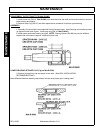
3.Gear backlash check procedure (Figure Mnt-R-0044). Install 1/2 x 3 capscrew through shear pin
hole. Install flat washers to take up 1/2" space and then install nut and tighten so bolt cannot move.
Clamp gearbox to something solid so it will not move when shaft is rotated by hand. Measure 1-1/2
inches from side of shaft to point on bolt and mark (See Figure Mnt-R-0044). Set dial indicator at
marked point, then while holding bottom shaft so it will not rotate, rotate the input shaft back and forth
noting extreme indicator reading. If total indicator deflection reading does not fall between .006 to
.018, then shims (Ref. #12 Figure Mnt-R-0040) will have to be added to increase backlash or deleted
to decrease backlash.


