


ASSEMBLY
148 02/11 Assembly Section 3-4
© 2011 Alamo Group Inc.
ASSEMBLY
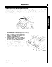
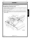
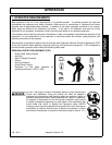
TAIL WHEEL INSTALLATION (Standard or Quick Hitch)
1. Align Tailwheel Beam Weldment (5) between
pivot brackets located behind gearbox mount
on Mainframe Weldment. NOTE: Long side of
caster fork pivot tube is positioned up. Attach
the Tailwheel Beam Weldment (5) to the
Mainframe Weldment with one 5/8” x 3-1/2” Bolt
(23), and 5/8” Nut (21). Slide Tail Wheel Beam
Weldment (5) into Gauge Wheel Mount
Weldment (1) and retain with two 1/2” x 3-1/4”
Bolts (22), and Locknuts (13).
2. Insert the Caster Fork Weldment (2) into
Tailwheel Beam Weldment (5) and retain with
Flatwasher (6) and Cotter Pin (7).
3. Tighten all bolts to the proper torque. Figure
Asm-R-0248
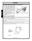
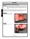
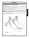
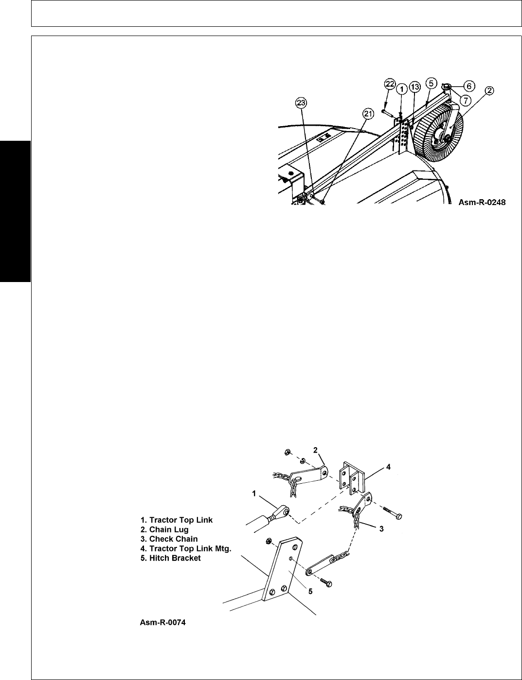
HYDRAULIC RELIEF ASSEMBLY
Hydraulic Relief Assembly (3570), also known as check chain, is available for attachment to front of cutter as
an accessory. Check chains are used to control cut height and especially allows cutter to always be lowered to
the same preset cut height. (Figure Asm-R-0074)
Drill a 11/16” hole through each lifting lug 2-1/2” below the lift pins and 5/8” from the front of the lug.
Install lower end of check chain (3) to hitch ears, through lower holes using capscrews and lockwashers.
Tighten securely.
Install chain lugs (2) on either side of tractor top link mounting (4) using bolt or pin of required diameter and
length. Cat. I kit requires a 3/4” diameter bolt. Install top end of check chains in brackets (2).
Cutting height is then set by placing proper chain link in keyhole slot. Cutting height is easily adjustable
hooking chain higher or lower in the keyhole brackets (2).