


23
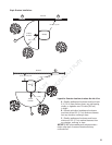
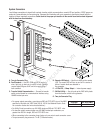
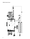
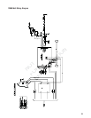
Generator AC Connection System
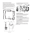
A single-phase, three-wire AC connection system is used
in the generator. The stator assembly consists of a pair
of stationary windings with two leads brought out of each
winding. The junction of leads 22 and 33 forms the neutral
lead, as shown schematically and as wiring diagram.
A complete schematic and wiring diagram can be found later
in this manual.
NOTICE Neutral is not bonded to ground at generator.
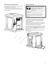
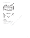
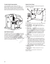
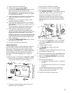
The conduit (A) between the corner electrical inlet and the
control panel is a UL requirement. If removed, it must be
replaced with similar conduit.
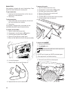
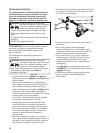
Grounding the Generator
Ground the generator per applicable codes, standards, and
regulations. The generator GND lug is located inside the
control panel door under the circuit breaker cover.
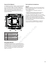
Utility Circuit Connection
i76UJMJUZwMFBETNVTUCFSPVUFEJODPOEVJU5IF
i76UJMJUZwMFBETEFMJWFSQPXFSUPUIFHFOFSBUPSTDJSDVJU
board, optional battery warmer and optional oil warmer. This
power also charges the battery. When power on these leads
is lost, the generator will start.
Using provided 2 pin connector plug and installer-supplied
minimum 300V, 14 AWG wire, connect each control circuit
terminal in the generator to the two-amp fuse terminals in
the automatic transfer switch.
When making connections, obey wire type and torque
specifications printed on the circuit breaker and neutral/
ground connector.
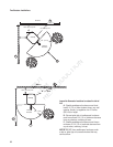
33
240V
11
22
44
120V
120V
1122 440
To Transfer Switch
Power Winding
Ground Neutral
Line 2 Line 1
Neutral
Circuit
Breaker
Circuit
Breaker
A
NOT
NO
N
T
4444
T
FOR
FOR
O
1111
FO
Ci iCi
Circui
Break
REPRODUCTION
ion
on
TU
CFCF
SPVUFE
SPVUFE
EFMJWFSFMJWFS
QPXFQPX
attery warmeattery warm
arges the batarges the b
generator wigenerator w
rovided 2 pinovided 2 p
mum 300V, mum 300V,
rminal in therminal in th
the automahe autom
When mWhen m
specspe
gg
RE
R