


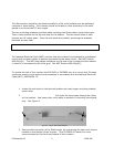
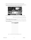
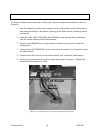
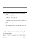

Figure 7: AC and PV Grounding
2.3.b Connecting the StarInverter to the Electrical Grid
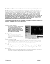
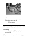
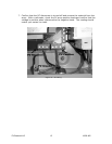
Inside the StarInverter are two circuit boards:
♦
♦
The Control Board
The Power Distribution Board with a D-sub socket or an optional terminal block
for communications to a personal computer and:
• The AC connection terminal
• The DC connection terminal
• The Internal AC grid fuse(s)
WARNING: For continued protection against risk of fire, replace only with
same type and ratings of fuse. For models PVP1800 and PVP2800 use only
Littelfuse 326020 20 AMP 250V AC.
PV Powered provides overcurrent protection on the Power Distribution Board with two 20
AMP fuses (See warning above). Overcurrent protection is also provided with the included
DC/GFI circuit breakers on the PVP1800 and PVP2800. Additional overcurrent protection
for the inverter’s AC output is provided by circuit breakers at the breaker panel.
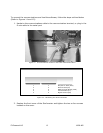
The StarInverter is connected to the electrical grid using 3 wires - the LINE, LINE
2/NEUTRAL and GROUND.
Please Note: To avoid an increase in AC voltage to unacceptable values while the
StarInverter is connected, the grid impedance value at the connection point should
be as low as possible. By keeping the grid impedance value low, higher system
efficiency will be achieved.
The total impedance of the grid plus the interconnecting AC wires should be less than
1.25 Ohm.
PV Powered LLC 9 18-28-405