


10
www.remingtonpowertools.com
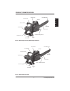
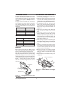
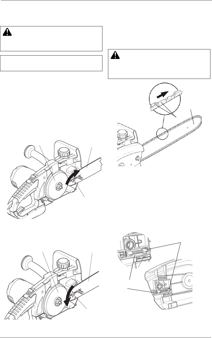
Towards
Guide Bar
Nose
Cutting
Edge
Guide Bar
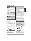
Chain Tensioning
Screw
Turn tensioning
screw to move
Adjustment Block
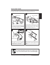
L
O
C
K
E
D
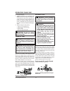
Guide Bar Retainer
Rotated 90 Degrees to
Guide Bar Slot
Guide Bar
Drive Sprocket
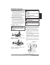
U
N
L
O
C
K
E
D
Guide Bar Retainer
Positioned Parallel
to Guide Bar Slot
Guide Bar
Drive Sprocket
Note: Some models are pre-assembled. Assembly
is not needed on these models. See Saw Chain
Tension Adjustment
1. Lay chain out flat.
2. Loosen and remove guide bar nut and sprocket
cover.
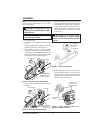
3. Rotate guide bar retainer so that it is positioned
parallel to guide bar slot (see Figure 2).
4. Install guide bar onto saw body. Assemble
center slot of guide bar onto guide bar bolt
and guide bar retainer. Note: Make sure the
head of the guide bar retainer slides through
the guide bar slot as shown in Figure 2.
WARNING: Cutting edges on chain
are sharp. Use protective gloves when
handling chain.
IMPORTANT: Do not clamp chain saw
in vise during assembly.
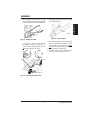
Figure 3 - Locking Guide Bar Retainer
5. Rotate guide bar retainer 90 degrees as shown
in Figure 3.
Figure 2 - Unlocking Guide Bar Retainer
ASSEMBLY
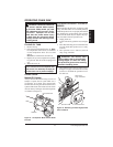
Figure 5 - Chain Tensioning Screw and
Adjustment Block Location
7. Before installing sprocket cover to saw body,
turn the chain tensioning screw fully counter-
clockwise until it stops. This will position the
adjusting block towards the end of the chain
tensiong screw. (See Figure 5)
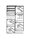
Figure 4 - Saw Chain Direction
6. Place chain around drive sprocket, along top
groove of guide bar, and around guide bar nose.
Note: Make sure cutting edges of chain are
facing in right direction. Position chain so
cutting edges on top of guide bar face guide
bar nose (see Figure 4 and indicator on side
cover of saw).
CAUTION: Do not place chain
on saw backwards. If chain is back-
wards, saw will vibrate badly and will
not cut.