


9
ENGLISH
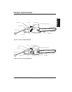
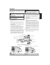
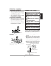
Guide Bar Nuts
Sprocket Cover
Drive Sprocket Screw or E-Ring
Sprocket Support Guide Bar Bolts
Saw Chain
Guide Bar
Drive Sprocket
Cutting Edge
Adjusting
Hole
Towards Guide Bar Nose
Note: Some models are pre-assembled. Assembly
is not needed on these models. See Saw Chain Ten-
sion Adjustment.
1. Lay chain out flat.
2. Loosen and remove guide bar nuts and sprocket
cover.
3. Loosen and remove drive sprocket screw or re-
move E-ring from shaft (see Figure 4). Remove
sprocket support.
4. Install guide bar onto saw body. Assemble center
slot of guide bar onto guide bar bolts.
5. To replace sprocket support, repeat step 3 in re-
verse order. Firmly tighten drive sprocket screw
with #2 Phillips screwdriver (if applicable).
6. Place chain around drive sprocket, along top
groove of guide bar, and around guide bar nose.
Note: Make sure cutting edges of chain are fac-
ing in right direction. Position chain so cutting
edges on top of guide bar face guide bar nose (see
Figure 4, and indicator on side cover of saw).
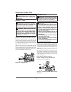
WARNING: Cutting edges on chain
are sharp. Use protective gloves when
handling chain.
IMPORTANT: Do not clamp chain saw in
vise during assembly.
7. Insert tab of sprocket cover into slot on side cover
and rotate sprocket cover onto guide bar bolts
until sprocket cover rests against guide bar.
8. Place guide bar nuts, removed in step 2, over
guide bar bolts.
IMPORTANT: Tighten guide bar nuts fi nger tight
only.
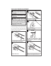
9. Turning chain tensioning knob (Model
RM1635W) or chain tensioning screw
(Model RM1632A), adjust position of adjust-
ment block until it is aligned and inserted into the
round adjusting hole on guide bar (see Figure 4,
5and 6). Turning chain tensioning knob or chain
tensioning screw counterclockwise will move
adjustment block to rear of guide bar. Turning
chain tensioning knob or chain tensioning screw
clockwise will move adjustment block to front
of guide bar.
10. If needed, readjust guide bar nuts to fi nger tight only.
11. Adjust saw chain tension. Follow steps under
Saw Chain Tension Adjustment.
CAUTION: Do not place chain on saw
backwards. If chain is backwards, saw
will vibrate badly and will not cut.
Figure 4 - Assembling Guide Bar and Chain
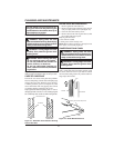
Figure 5 - Turn Chain Tensioning Screw on
Model RM1632A
Figure 6 - Turn Chain Tensioning Knob on Model
RM1635W
Chain Tensioning Screw
Adjustment
Block
Chain Tensioning Knob
Adjustment Block
E-Ring
ASSEMBLY