


5
Table 3: Design Ratings
P
ressure
T
emperature
Tubeside 235 PSI 406°F
Shellside 190 PSI 406°F
Model
Boiler
Flow
Boiler
Head Loss
Pool
Flow
Pool
Head Loss
Heating
Surface
SS316L
CR24
Super Alloy
GPM Feet GPM Feet
Sq. Ft.
Min Max Min Max Min Max Min Max
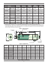
RP-045 5 15 0.5 1.0 20 40 1.5 6.0 2.0
RP-075 10 20 1.0 2.5 20 50 1.5 7.0 2.8
RP-125 10 20 1.0 2.5 20 50 2.0 10.0 3.3
RP-185 CR24-185 20 30 1.0 2.0 20 50 1.5 9.5 4.9
RP-245 20 30 1.0 2.5 30 60 2.5 9.0 7.3
RP-305 CR24-305 20 35 1.5 4.0 30 60 1.5 6.0 9.4
RP-495 CR24-495 25 35 3.5 6.5 40 80 3.0 12.0 17.3
RP-995 50 100 4.0 13.0 70 120 5.5 15.0 23.7
Designed and fabricated to the
ASME B31.3 Process Piping Code
Installation Guidelines
Plumbing
Connections to the Indirect Pool Heater must be made
with materials that have similar galvanic properties to
the passivated 316 stainless steel or CR24 super alloy
of the heat exchanger. Connections to the heat source
plumbing should be made with 300 series stainless
steel nipples. Dielectric unions are recommended if
dissimilar plumbing is used. Connections to the pool
system should be made with CPVC or PVC adapters
or 300 series stainless steel nipples. Dielectric unions
are recommended if dissimilar plumbing is used.
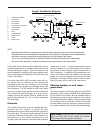
The connection diagram, Figure 2, is shown for refer-
ence only. The system must be designed and installed
by a qualified installer and all local, state, provincial
and national codes, laws, regulations and ordinances
must be followed.
Flow
For optimal heat transfer, counter flow should be uti-
lized, that is the supply water from the heat source
should flow in the opposite direction of the return water
from the pool/spa, as shown in the connection dia-
gram, Figure 2. Systems must be designed to provide
flow rates within the range provided in Table 4. Do not
exceed the published maximum flow rates. On the
heating side, desired flow rates can be accomplished
with the pump sizing and/or use of balancing valves.
Table 4: Flow & Pressure Drop Specifications