


23
INTERNAL AUTOMATIC BYPASS VALVE
In addition to the Unitherm Governor, a built-in auto-
matic bypass valve is provided in the in/out header.
While the Unitherm Governor responds to the changes
in water temperature in the heater, the internal bypass
valve automatically responds to changes in water
pressure in the piping system. Proper amount of water
flow is maintained through the heater under varying
pressures dictated by the conditions of the pump and
filter.
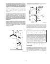
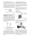
EXTERNAL AUXILIARY BYPASS VALVE
(Where Required)
An auxiliary bypass valve should be used when flow
rates exceed 125 GPM. Usually a high-performance
pump size larger than two horsepower will exceed this
flow rate. This valve is required to complement the
function of the automatic bypass valve, particularly
when starting the heater in winter or early spring when
the spa or pool temperature is below 50°F. It also
serves to eliminate needless pressure drop through
the heater and accompanying reduction in the flow
rate to the spa jets, etc.
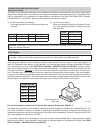
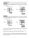
From Heater To Heater
To Pool/ From Pool/
Spa Spa
AUXILIARY BYPASS VALVE
(DO NOT USE GATE VALVE)
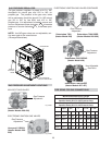
Bypass Disc
Spring
Bypass Body
Fig.# 2003
Fig.# 81.50.0
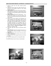
AUXILIARY BYPASS VALVE ADJUSTMENT
To set bypass: With clean filter, adjustment is made by
feeling the inlet and outlet pipes at the heater. Outlet
pipes should be slightly warmer than inlet and comfort-
able to the touch. If pipe is hot, close bypass; if cold,
open bypass.
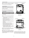
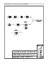
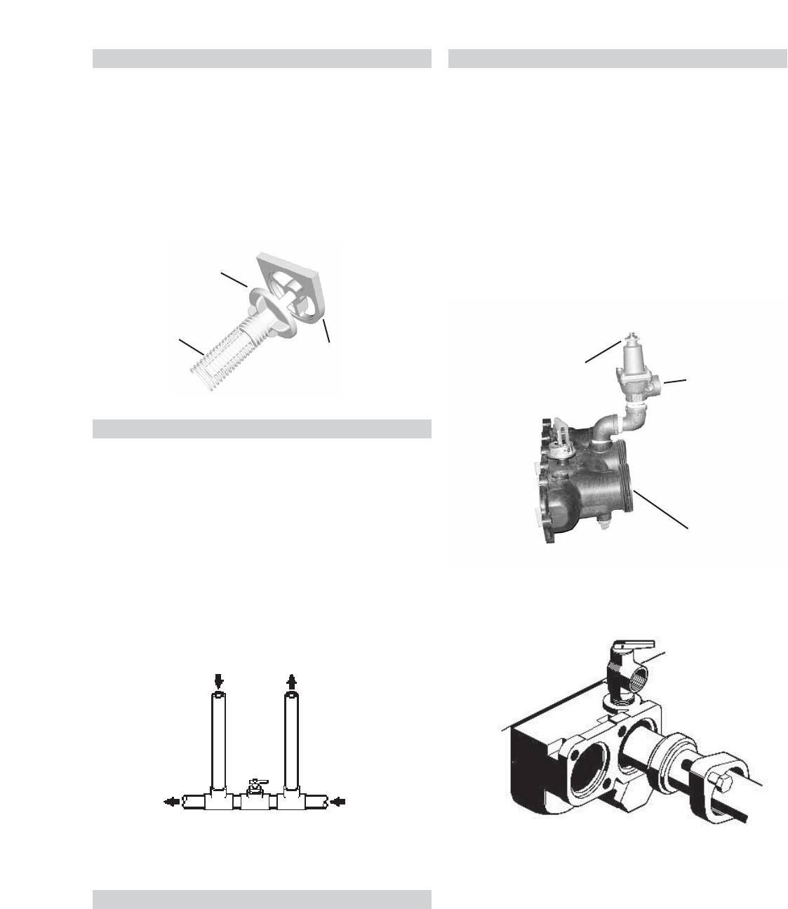
PRESSURE RELIEF VALVE INSTALLATION
To conform to local building codes, it may be neces-
sary to install a pressure relief valve. A 3/4" pressure
relief valve, having a capacity equal to the BTUH out-
put of the model to be installed, is recommended for
this heater. The maximum acceptable pressure relief
valve setting is 125 psi.
A 3/4" NPT connection is provided in the Polymer
header for installation of a pressure relief valve. The
valve shall be installed in a vertical position. Do not
overtighten. Install pressure relief valve hand tight
plus 1/2 turn.
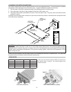
POLYMER HEADER
(STANDARD MODELS)
Pressure Relief Valve
PRV Discharge
Connection
In/Out Header
Fig. #2004
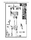
A 3/4" NPT connection is provided in the header for
installation of a pressure relief valve. The valve shall
be installed in a vertical position.
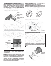
CAST IRON HEADER
(ASME MODELS)
NOTE:
To avoid water damage or scalding due to
valve operation, drain pipe must be connected to valve
outlet and run to a safe place of discharge. Drain pipe
must be the same size as the valve discharge connec-
tion throughout its entire length and must pitch down-
ward from the valve. No shut-off valve shall be
installed between the relief valve and the drain line.
Valve lever should be tripped at least once a year to
ensure that waterways are clear.
PRV