


19
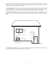
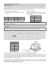
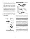
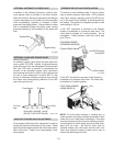
The discharge opening must be a minimum of 2 ft ver-
tically from the roof surface and at least 2 ft higher than
any part of the building within 10 ft. Vent stack shall be
at least 5 ft in vertical height above the drafthood out-
let. The vent cap location shall have a minimum clear-
ance of 4 ft horizontally from, and in no case below,
unless a 4 ft horizontal distance is maintained, from
electric meters, gas meters, regulators and relief
equipment.
The weight of the vent stack or chimney must not rest
on heater drafthood. Support must be provided in
compliance with applicable codes. The heater top and
drafthood must be readily removable for maintenance
and inspection. Vent pipe should be adequately sup-
ported to maintain proper clearances from combustible
construction.
Type "B" double-wall or equivalent vent pipe is recom-
mended. However single-wall metal vent pipe may be
used as specified in the latest edition of the National
Flue Gas Code ANSI Z223.1 (Canada - CAN/CGA-
B149.1 and B149.2).
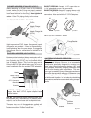
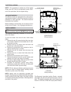
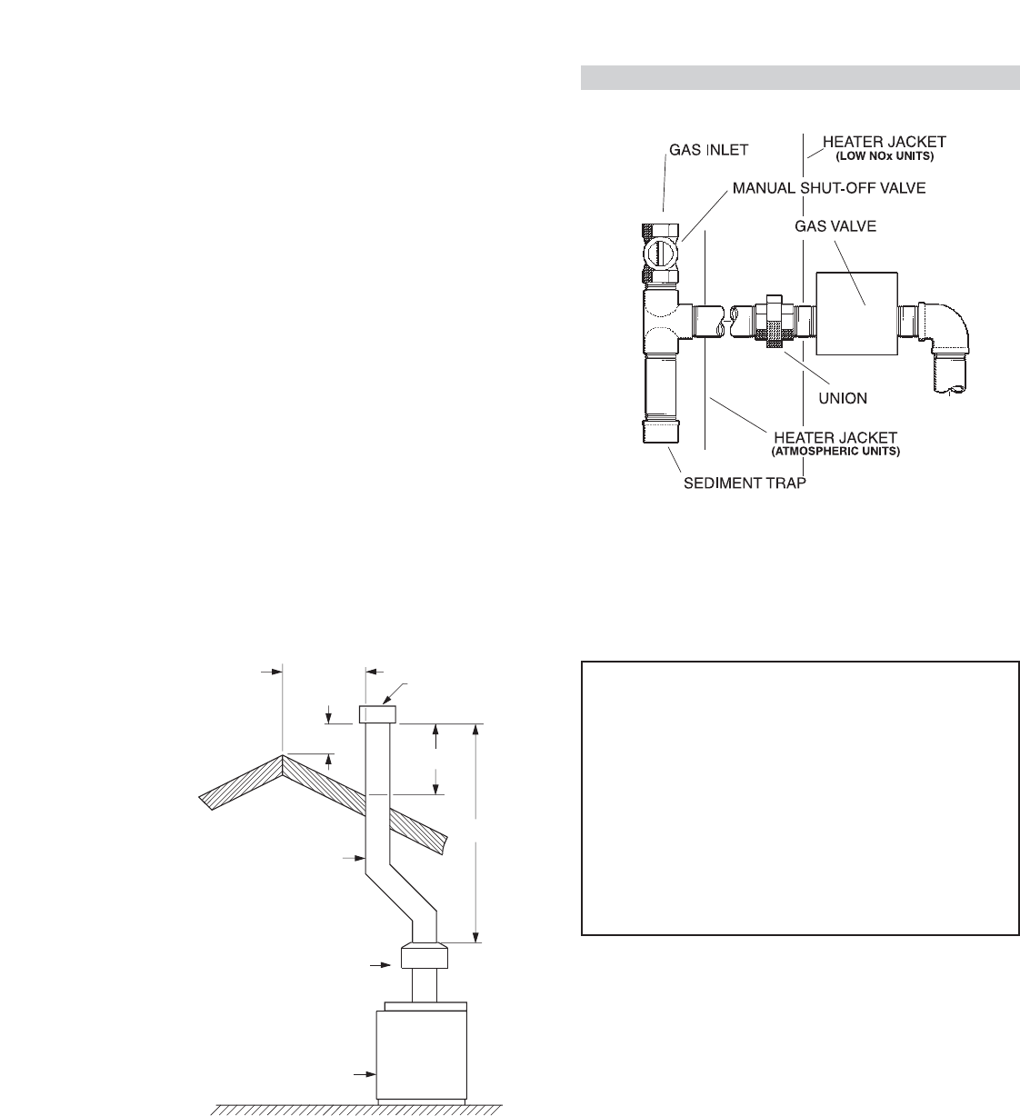
GAS SUPPLY CONNECTIONS
Gas piping must have a sediment trap ahead of the
heater gas controls, and a manual shut-off valve locat-
ed outside the heater jacket. All gas piping should be
tested after installation in accordance with local codes.
CAUTION:
The heater and its manual shut-off valve
must be disconnected from the gas supply during any
pressure testing of that system at test pressures in
excess of 1/2 psig (3.45 kPa). Dissipate test pressure
in the gas supply line before reconnecting the heater
and its manual shut off valve to gas supply line. FAIL-
URE TO FOLLOW THIS PROCEDURE MAY DAM-
AGE THE GAS VALVE. OVER PRESSURIZED GAS
VALVES ARE NOT COVERED BY WARRANTY. The
heater and its gas connections shall be leak tested
before placing the appliance in operation. Use soapy
water for leak test. DO NOT use open flame.
5' MIN
2' MIN
10' OR LESS
2' MIN
VENT CAP
VENT PIPE
DRAFT HOOD
HEATER
Fig.# 8119.2
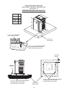
Fig.# 8090.1
NOTE:
Do not use Teflon tape on gas line pipe thread.
A flexible sealant suitable for LP gases is
recommended.
A minimum of 7 in. WC and a maximum of 14 in. WC
upstream pressure under load, and no-load conditions
must be provided for natural gas or a minimum of
12 in. WC and a maximum of 14 in. WC for propane
gas.