


10
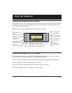
Calibrating
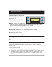
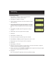
Calibrating Outputs
1. Select Options > Calibrate > Reset to set the generator’s
calibration factors to default nominal values.
2. Press Options > Calibrate > Full Scale.
3. Set the voltmeter’s scale factor to be able to measure a nominal
1000 millivolts DC.
4. Using a VGA-to-BNC cable, connect the generator’s red output to
the positive input on the voltmeter, with a 75 ohm (+/- 1%) input
terminator. Connect the negative lead of the meter to any ground
pin.
5. Select R_FS+ or -R_FS to set the DC output level to 1000 mV
+/- 3 mV.
6. Repeat steps 4 and 5 for the green and blue outputs.
7. Select Save.
8. Select Options > Calibrate > Zero.
9. Connect the red output to the positive input of the voltmeter.
10. Select R_Zero+ or -R_Zero to set the DC output level to 0 mV +/- 3 mV.
11. Repeat steps 9 and 10 for the green and blue components.
12. Select Save.
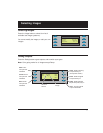
13. Select Options > NTSC_CAL.
14. Adjust the oscilloscope's timebase and sweep trigger to view the entire waveform. Adjust the
G_NTSC so that its chrominance is 100 IRE or 714mV.
15. Using a vector scope, use the R_NTSC and B_NTSC options to adjust the red and green outputs
using so that their signals align with the 2% boxes.
16. Press Save.
Note: The modulated RF output does not have any calibration settings.
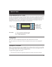
_____ Calibrate
_
_
Full_Scale____ Zero
_Reset
_R_FS+_____ ___-R_FS
_G_FS+_______ _-G_FS
_B_FS+_______ _-B_FS
_Save_________ _Back
_R_Zero+____ -R_Zero
_G_Zero+____ -G_Zero
_B_Zero+____ -B_Zero
_Save__________ Back