


TOOLS REQUIRED: 7/16”, 1/2” and 9/16" sockets and ratchets, block(s) of wood (minimum of 6” tall).
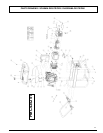
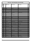
Refer to the parts list and drawing on pages 8 and 9.
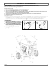
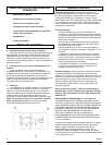
WHEEL INSTALLATION
1. Block up end of generator opposite the fuel tank cap to install wheel kit.
2. Insert wheel spacer (item 46) into the center of the wheel (item 31).
3. Slide 3/8 x 4.25” bolt (item 35) and 3/8 washer (item 47) through the wheel (item 31), then through the wheel bracket on the
carrier, with the offset side of the wheel hub against the wheel bracket.
4. Thread 3/8 nyloc nut (item 36) onto the bolt and tighten to securely clamp the wheel assembly to the carrier.
5. Repeat above instructions for the remaining wheel.
FOOT INSTALLATION
1. Blocking up the engine side of the generator, place the foot bracket (item 30) under the carrier channel. Thread a 5/16-18 x 4”
bolt (item 45) with a rubber foot (item 32) through the mounting holes and thread a 5/16 flange nut (item 15) to the bolt to
secure the foot bracket to the carrier. Caution: Do not over tighten so that the rubber foot material collapses.
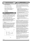
LOCKING HANDLE
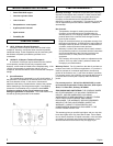
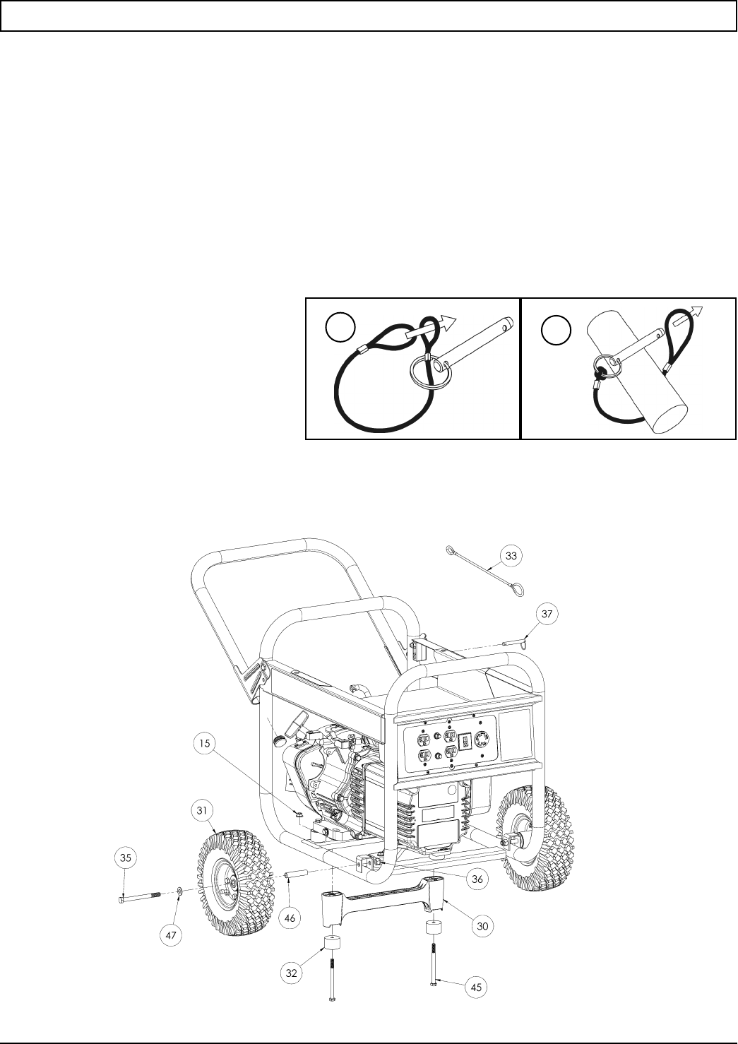
1. Attach the lanyard (item 33) to the release pin
(item 37) and carrier as shown in the illustration.
2. To lock the handle (item 28) in the extended
position, align the holes in the handle bracket
with the holes in the carrier bracket and insert
the release pin (item 37).
3. Insert caps (item 38) into ends of handle
(item 28).
3
English
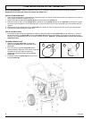
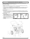
PORTABILITY KIT INSTALLATION
1
2