


*9 HP Briggs & Stratton OHV engine
*Cast-iron cylinder sleeve
*Low oil sensor
*Muffler guard
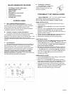
*Receptacles on control panel
*CordKeeper™
*5 gallon plastic fuel tank
*Portability Kit
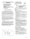
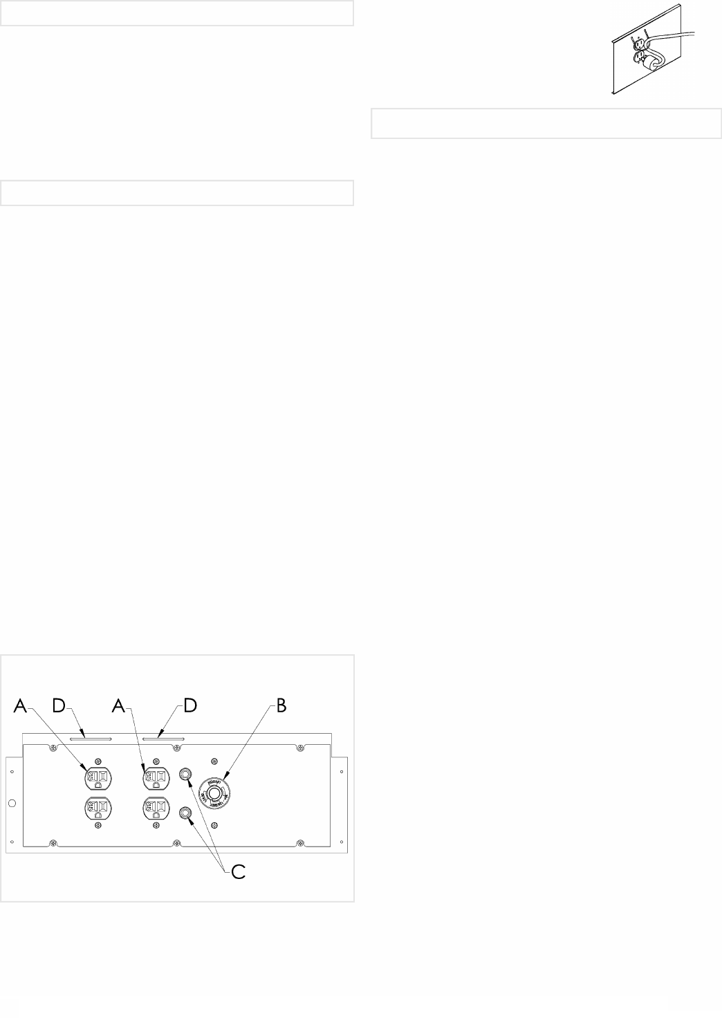
A.120 V, 20 Ampere Duplex Receptacle
This duplex is split so that 20 amps of current may be
drawn from each half of the receptacle. However, total power
drawn must be kept within nameplate ratings. These
receptacles may be used along with the twistlock receptacle
provided the generator is not overloaded.
B.120/240 V, 30 Ampere Twistlock Receptacle
A maximum of 30 amps may be drawn from the 120/240
volt receptacle, provided it is the only receptacle used.
However, current must be limited to the nameplate rating. If the
120/240 volt receptacle is used along with the 120 volt
receptacle, the total load drawn must not exceed the nameplate
ratings.
C.Circuit Breakers
The receptacles are protected by an AC circuit breaker. If
the generator is overloaded or an external short circuit occurs,
the circuit breaker will trip. If this occurs, disconnect all
electrical loads and try to determine the cause of the problem
before attempting to use the generator again. If overloading
causes the circuit breaker to trip, reduce the load. NOTE:
Continuous tripping of the circuit breaker may cause
damage to generator or equipment. The circuit breaker may
be reset by pushing the button of the breaker.
D.CordKeeper™ Restraint
The CordKeeper™ restraint is a
unique feature used to prevent
plugs from being pulled out of the
120-volt receptacles.
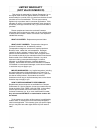
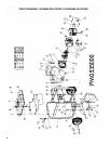
TOOLS REQUIRED: 7/16”, 1/2”, 9/16”, and 5/8" sockets
and ratchets, block(s) of wood (minimum of 6” tall).
Refer to the parts list and drawing on pages 8 and 9.
WHEEL INSTALLATION
1.Block up end of generator opposite the fuel tank cap to
install wheel kit.
2.Insert wheel spacer (item 37) into the center of the wheel
(item 31).
3.Slide 3/8 x 4.25” bolt (item 35) and 3/8 washer (item 38)
through the wheel (item 31), then through the wheel
bracket on the carrier, with the offset side of the wheel hub
against the wheel bracket.
4.Thread 3/8 nyloc nut (item 36) onto the bolt and tighten to
securely clamp the wheel assembly to the carrier.
5.Repeat above instructions for the remaining wheel.
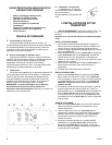
FOOT INSTALLATION
1.Assemble the rubber feet (item 32) to the foot bracket (item
41) using a 1/4-20 x 1.5” bolt (item 40). Thread a 1/4
washer (item 39) and a 1/4 nyloc nut (item 13) to the bolt to
secure the assembly. Caution: Do not over tighten so
that the foot material collapses.
2.Blocking up the alternator side of the generator, place the
foot bracket under the carrier channel. Thread a 5/16-18 x
1” bolt (item 33) with a 5/16 washer (item 34) through the
mounting holes and thread a 5/16 washer (item 34) and a
5/16 nyloc nut (item 16) to the bolt to secure the foot
bracket to the carrier.
HANDLE INSTALLATION
1.Place handle (item 28) over carrier tubing on same end as
feet, centering handle on the carrier.
2.Slide 7/16 x 2” bolt (item 29) through handle as shown in
diagram and secure with 7/16” nyloc nut (item 27). Tighten
until handle is securely clamped to the carrier tubing.
3.Apply aerosol hairspray or similar adhesive to the handle
(item 28), and then slide the handle grip (item 30) onto the
handle. The aerosol hairspray will allow for easier
assembly and will adhere the grip to the handle.
2
English
CONTROL PANEL
MAJOR GENERATOR FEATURES
PORTABILITY KIT INSTALLATION