


TOOLS REQUIRED: 7/16”, 1/2”, 9/16", and 5/8” sockets and
ratchets, block(s) of wood (minimum of 6” tall).
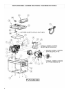
Refer to the parts list on page 9.
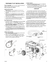
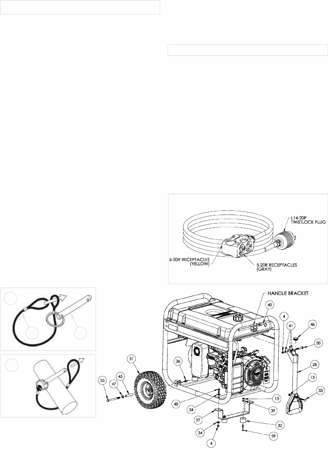
WHEEL INSTALLATION
1.Block up end of generator opposite the fuel tank cap to
install wheel kit.
2.Insert wheel spacer (item 45) into the center of the wheel
(item 31).
3.Slide 3/8 x 4.25” bolt (item 35) and 3/8 washer (item 47)
through the wheel (item 31), then through the wheel
bracket on the carrier, with the offset side of the wheel hub
against the wheel bracket.
4.Thread 3/8 nyloc nut (item 36) onto the bolt and tighten to
securely clamp the wheel assembly to the tubing.
5.Repeat above instructions for the remaining wheel.
FOOT INSTALLATION
1.Assemble the rubber feet (item 32) to the foot bracket (item
27) using a 1/4-20 x 1.5” bolt (item 29). Thread a 1/4
washer (item 39) and a 1/4 nyloc nut (item 13) to the bolt to
secure the assembly. Caution: Do not over tighten so
that the foot material collapses.
2.Blocking up the alternator side of the generator, place the
foot bracket under the carrier channel. Thread a 5/16-18 x
1” bolt (item 48) with a 5/16 washer (item 34) through the
mounting holes and thread a 5/16 washer (item 34) and a
5/16 nyloc nut (item 4) to the bolt to secure the foot bracket
to the carrier.
HANDLE INSTALLATION
1.Place handle (item 28) over carrier tubing on same end as
feet, centering handle on the carrier.
2.Slide 5/16 x 2.25” bolt (item 30) through handle, handle
bracket, and 5/16 washers (item 41) as shown in diagram
and secure with 5/16” nyloc nut (item 4). Tighten until
handle is securely clamped to the bracket.
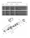
LOCKING HANDLE
1.Attach the lanyard (item 44) to the release pin (item 40)
and carrier as shown in the illustration.
2. To lock the handle (item 28) in the extended position, align
the holes in the handle bracket with the holes in the carrier
bracket and insert the release pin (item 40).
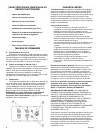
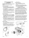
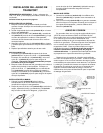
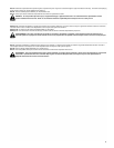
Your generator is supplied with a 25 foot 12 GA SJTW
4-conductor 105ºC power cord set. This cord is equipped with
an L14-20P twistlock Plug, on one end, which will plug directly
into the mating twistlock receptacle on the control panel of your
generator. The opposite end comes equipped with a special 4
circuit connector comprised of four 5-20R receptacles. These
may be used to power individual loads. Make sure the loads
do not exceed the 20 amp rating of the Power Cord Set.
Circuit breaker protection is provided for on the control panel of
your generator.
You will notice that the 4-circuit connector is color coded
with gray and yellow receptacles. When several loads are
powered at the same time, it is best to keep equal loads
supplied to each separately colored half, if possible. The gray
half and the yellow half of the connector are each capable of
sustaining 20 amps of current provided your generator is
capable of supplying 4800 watts of power. Check nameplate
ratings for total wattage capability of the generator.
3
English
PORTABILITY KIT INSTALLATION
CORD SET
2
1
4044