


8
Customer Hotline 1-800-445-1805English
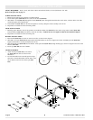
TOOLS REQUIRED: 10mm, 13mm, and 16mm sockets and ratchets, block(s) of wood (minimum of 6” tall).
Refer to the parts list on page 37.
WHEEL INSTALLATION
1.Block up the engine end of generator to install wheel kit.
2.Insert wheel spacer (item 165) into the center of the wheel (item 166).
3.Slide M10 x 75 bolt (item 167) through the wheel (item 166), then through the wheel bracket on the carrier, with the offset side of the
wheel hub against the wheel bracket.
4.Thread M10 nut (item 163) onto the bolt and tighten to securely clamp the wheel assembly to the carrier.
5.Repeat above instructions for the remaining wheel.
FOOT INSTALLATION
1.Blocking up the alternator side of the generator, assemble the rubber foot (item 161) to the carrierusing a M8 x 20 bolt (item 160).
Thread a M8 nut (item 162) to the bolt to secure the assembly. Caution: Do not over tighten so that the foot material collapses.
2.Repeat above instructions for the remaining foot.
HANDLE INSTALLATION
1.Place handle (item 156) on carrier on same end as feet, as shown in the diagram.
2.Slide M8 x 40 screw (item 153) through handle and handle bracket as shown in diagram and secure with M8 nyloc nut (item 155).
Tighten until handle is securely clamped to the carrier.
3.Slide the handle grip (item 158) onto the handle. Slide square bolt (item 157) through handle grip as shown in diagram and secure with
M6 nut (item 159).
4.Insert cap (item 154) into end of handle.
LOCKING HANDLE
1.Attach the lanyard (item 151) to the release
pin (item 152) and carrier as shown in the
illustration.
2. To lock the handle in the extended position, align
the holes in the handle bracket with the holes in the
carrier bracket and insert the release pin (item
152).
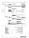
PORTABILITY KIT INSTALLATION
1
2
152151