


5
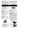
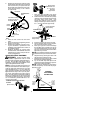
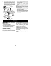
2. Position the clamp base under the upper
shaftandaligntheshaft clampandclamp
base screw holes (use spacer tabs be-
tweenshaftclampandclampbase ifnec-
essary tosecure clamp, i.e.for1
"
diame-
ter upper shaft).
POWERHEAD
END
ATTACHMENT
END
Screws
Clamp
Base
Handlebar Clamp
between arrows on
handlebar decal
Clamp
Knob
Shaft
Clamp
Handlebar
Arrow on
Safety Decal
3. Insert the four screws into the screw
holes.
4. Secure shaft clamp by tighteningscrews
with the hex wrench.
5. Position the handlebaras shown, ensur-
ing the handlebar is positioned on the
handlebar clamp between the arrows on
the handlebar decal.
6. Retighten handlebar by turning clamp
knob clockwise until handlebar is secure
andstationaryin clamp (clamp knobcan-
not be overtightened).
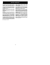
SHOULDER STRAP ASSEMBLY
W ARNING:
Proper shoulder strap
and handlebar adjustments must be made
withthe enginecompletely stoppedbeforeus-
ing unit. The shoulder strap clamp must be
installed as shown above the handlebar on the
upper shaft (powerhead end of unit).
NOTE:
The lower shoulder strap clamp has
twospacertabsattached. Thesetabsarepro-
vided to adapt this attachment for use with
powerheads that have a 1
"
(2.5cm) diameter
upper shaft (the shoulder strap clamp will not
tightendownsecurelyonthe1
"
(2.5cm)diam-
eter upper shaft without using these spacer
tabs). Thetabsmust bebrokenoffcompletely
before use and placed over the screw holes
onthelowershoulderstrapclamp. Thesetabs
are not needed for powerheads with a 7/8
"
(2.2 cm) upper shaft.
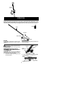
Spacer Tabs
LOWER SHOULDER STRAP
CLAMP
Spacer Tabs
positioned for use
on 1
"
(2.5 cm)
diameter
upper shaft
1. Place the upper shoulder strap clamp
overtheuppershaftabovethehandlebar.
2. Position the lower shoulder strap clamp
underthe uppershaft andalign theupper
and lower clamp screw holes (use
spacer tabs between upper and lower
clamps if necessary to secure clamp, i.e.
for 1
"
(2.5 cm) diameter upper shaft).
Upper Shoulder
Strap Clamp
Screws
Lower Shoulder
Strap Clamp
POWERHEAD
END
ATTACHMENT
END
3. Insert two screws into the screw holes.
4. Secure shoulder strap clamp by tighten-
ing screws with the hex wrench.
5. Insert your right arm and head through
the shoulder strap and allow it to rest on
your left shoulder. Make sure the danger
sign is onyourback andthehook is tothe
right side of your waist.
NOTE:
Aone-halftwist is builtin theshoulder
strapto a llow thestraptorest flatontheshoul-
der.
6. Adjust the strap, allowing the hook to be
about 6 inches below the waist.
7. Fasten the strap hook to the clamp and lift
the tool to the operating position.
8. Try on shoulder strap and adjust for fit
andbalancebeforestarting theengineor
beginning a cutting operation.
NOTE:
It may be necessary to relocate the
shoulder strap clamp on the shaft for proper
balancing of unit.
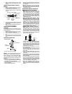
30 inches
(76 cm)
HARNESS
ADJUSTMENT
FOR BALANCE
6 inches
(15 cm)
below
waist
4--12
inches
(10 -- 30 cm)
above
ground