


6
damage in otherwise healthy peop le. If
symptoms occur such as numbness, pain,
loss of strength, change in skin color o r t exture,
or loss of fe eling in the fingers, hands, or jo ints,
discontinue t he use of this tool and seek
medical attention. An anti-vibration system
does not guarantee the avoidance of these
problems. Users who operate power tools on
a continual and regular basis must monitor
closely t heir physical condition and the
condition of this tool.
SPECIALNOT ICE:Yoursaw isequipped
with a temperature limiting muffler andspark
arresting screen which meets the
requirements o f California Codes 4442 and
4443. All U.S. forest land and the states of
California, Idaho, Maine, Minnesota, New
Jersey, Oregon, and Washington require by
law that many internal combustion engines
tobeequipped with aspark a rrestingscreen.
If youoperate achainsaw ina state o rlocale
where such regulations exist, you arelegally
responsible for maintaining t he operating
condition of these parts. F ailure to do so is
a violation of the law. Refer to the SERVICE
section for maintenance of the spark
arresting screen.
Failureto followall Safety Rules andPrecau-
tions can result inserious injury. If situations
occur which are not covered in this manual,
use care and good judgement. If you need
assistance, contact your authorized service
dealer or call 1-800--554--6723.
STANDARDS: This saw is listed b y U nd er-
writer’s Laboratories, Inc., and the Canadian
Standards Association in accordance with:
ANSI B175.1-2000 American National
Standard for Powered Tools -- Gasoline
Powered Chain S aw -- Safety Requirements
CSA Z62.1--03 Chain Saws -- Occupational
Health and Safety
CSA Z62.3--96 Chain Saw Kickback Occu-
pational Health and Safety
ASSEMBLY
Protective gloves (not provided) should be
worn during assembly.
AT TACHINGTHE BAR &CHAIN(If not
already attached)
WARNING: If r ecei ved a s sembled,
repeat all steps to ensure your saw is properly
assembled and all fasteners are secure. Al-
ways wear gloves when handling the chain.
The chain is sharp and can cut you even when
it is not mo ving!
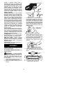
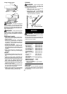
1. Loosen andremove thechain brakenuts
and the chain brake from the saw .
2. Remove the plastic shipping spacer (if
present).
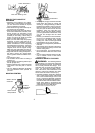
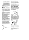
Chain Brake
Chain Brake
Nuts
Bar Tool
Location of shipping spacer
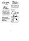
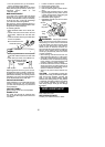
3. An adjusting pin and screw is used to ad-
just the tension of the chain. It is very im-
portant when assembling the bar, that the
pin located on the adjusting screw aligns
into ahole i n thebar . T urning t he screw will
move the adjustment pin up and down the
screw. Locate this adjustment before you
begin mounting the bar onto the saw . See
illustration below .
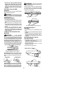
Adjustment located on Chain Brake
Inside view of
Chain Brake
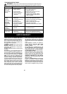
4. Turn the adjusting screw by hand coun-
terclockwise until the adjusting pin just
touches the stop. This should allow the
pin to be near the correct position.
5. Slide guide bar behind clutch drum until
guide bar stops against clutch drum
sprocket.
Mount the Bar
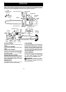
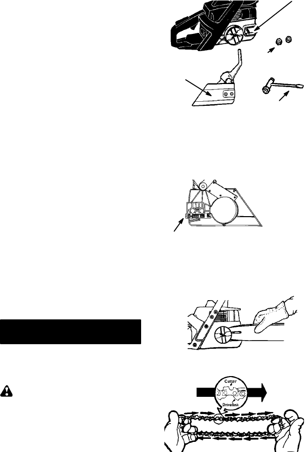
6. Carefully remove the chain from the pack-
age. Hold chain with the drive links as
sho wn .
CUTTERS MUST FACE IN
DIIRECTION OF ROTATION
Tip of
Bar