4
ASSEMBLY
WARNING: If received assembled,
review allassembly steps toensure your unit
is properly assembled and all fasteners are
secure.
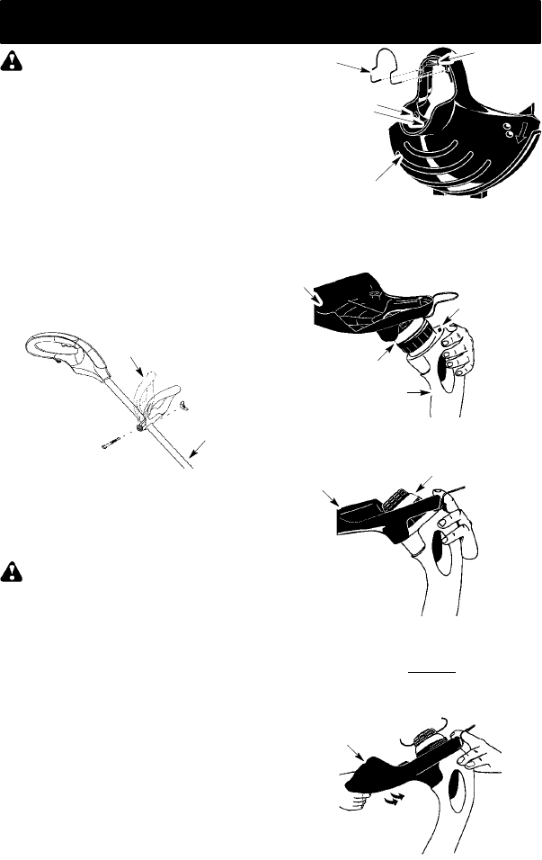
ADJUSTING ASSIST HANDLE
1. Loosen and remove wing nut and bolt
from assist handle.
2. Place unit on a flat surface.
3. Firmly push the assist handle over the
tube. Tomake installation easier, tilthan-
dle toward trigger housing while pushing
down (see illustration).
4. Reinstall bolt in handle. Thread wing nut
onto bolt.
5. Adjustthehandleupordownthetube toa
comfortable position; tightenwing nutse-
curely.
ATTA CH ING THE SHIELD
WARNING: The shield must beprop-
erly installed. The shield provides partial
protection t otheoperator andot hers fromthe
risk of thrown objects. Your unit is equipped
with a line limiter blade, which cuts excess
line to the proper length while running. The
line limiter blade (on underside of shield) is
sharp and can cut you.
NOTE: If shield is not p roperly installed, dam-
age to unit (including motor failure) will result.
1. Insert edge guide into two holes in shield.
NOTE: Edge guidemustbepositionedon
shield prior to installation on motor housing
(see following illustration).
Edge Guide
Shield
Rear Locking
Tabs
Front
Locking
Tab
2. Placeshieldovercuttingheadat anangle
to the motor housing. Insert front locking
tabonshield intoopeninginfront ofm otor
housing.
Opening for
Front
Locking Tab
Shield
Cutting Head
Motor Housing
3. Keep front locking tab inthe motor housing.
Cutting Head
Shield
4. Push shield toward motor housing until
rear locking tabs snap into rear notches.
An audible snap must be
heard. Ensure
the cutting head remains free to rotate
and the line is not caught between the
shield and the motor housing.
Shield


