


4
screen. Ifyouoperateinalocalewheresuch
regulations exist, you are legally responsible for
maintaining t he operating condition of these
parts. Failure to do so is a violation of the law.
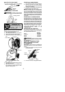
For normal homeowner use, the muffler and
spark arresting screen will not require any ser-
vice. After 50 hours of use, we recommend that
your muffler be serviced or replaced by your au-
thorized service dealer.
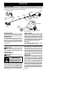
ASSEMBLY
CARTON CONTENTS
Check carton contents ag ainst the following
list:
S Powerhead
S Lower attachment (with trimmer head
installed)
S Cupped washer
S Large nut for installing blades
S Hex wrench
S Handlebar
S Bracket cover
S Bracket cover screws (2)
S Metal blade shield
S Blade shield screws (4)
S 4--point weed blade
S Plastic shield
S Wing nut (screwed onto plastic shield)
S Shoulder strap with warning
S Container of oil
WARNING: Alwaysstopunit anddis-
connectspark plugbeforeperforminganyas-
sembly procedures.
WARNING: If received assembled,
repeat allsteps toensure your unitis properly
assembled and all fasteners are secure.
Examine parts for dam age. Do not use dam-
aged parts.
NOTE: If you need assistance or find parts
missing or damaged, call 1-800-554-6723.
It is normal for the fuel filter to rattle in the
empty fuel tank.
Finding fuelor oil residue onmuffler isnormal
due to carburetor adjustments and testing
done by the manufacturer.
TOOLS REQUIRED
S Hex wrench (provided)
S Adjustable wrench
S Phillips screwdriver
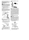
INSTALLING BRUSHCUTTER
ATTACH MENT
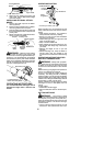
CAUTION:
When installing brushcutter at-
tachment, place the unit on a flat surface for
stability.
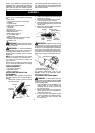
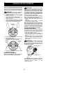
1. Loosen the coupler by tu rning the knob
counterclockwise.
Coupler
Knob
LOOSEN
TIGHTEN
Shipping
protector
2. Remove shipping protector fromcoupler.
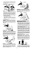
3. Remove the shaft cap from thebrushcutter
attachment (if present).
4. Position locking/release button o fattach-
ment into guide recess of coupler .
5. Pushtheattachmentintothe coupleruntil
the locking/release button snaps into the
primary hole.
6. Before using the unit, tighten the knob se-
curely by turning clockwise.
Coupler Primary Hole
Upper
Shaft
Locking/
Release
Button
Lower
Attachment
Guide Recess
WARNING: Make sure the locking/
release button i s locked in the primary hole
and theknob is securely tightened beforeop-
erating the unit.All attachments aredesigned
to be used in the primary hole unless other-
wise stated in the applicable attachment in-
struction manual. Using thewrong holecould
lead to serious injury or damage to the unit.
Locking/Release
Button in Primary Hole
Secondary Hole
For optional attachments, see the AS-
SEMBL Y section of the applicable attach-
ment instruction manual.
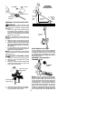
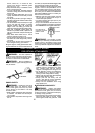
ATTACHING THE HANDLEBAR
DANGER: To avoid serious injury, the
barrierportion ofthe handlebar m ust beinstalled
as shown to provide a barrier between operator
and the spinning blade.
1. Locate the decal on the handlebar. This
decal includes an arrow . Position the
handlebar with the mounting bracket at
the end of the arrow.
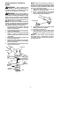
2. Position the bracket cover over the han-
dlebar. Again make sure thehandlebar is
at the end of the a rrow.
3. Insert screws and hand tighten only. Be
sure the handlebar is installed correctly;
then, tighten each screw securely with
the hex wrench.