


4
operate in alocale wheresuch regulations ex-
ist, you arelegally responsible formaintaining
the operating condition of these parts. Failure
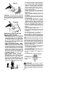
to do so is a violation of the law. For normal
homeowner use,the muffler and sparkarrest-
ing screen will not require any service. After
50 hours of use, we recommend that your
mufflerbe serviced orreplaced by yourautho-
rized service dealer.
ASSEMBLY
CARTON CONTENTS
Check carton contents against the following
list:
S
Brushcutter
S
Handlebar screws (2)
S
Blade shield screws (4)
S
Cupped washer
S
Large nut for installing blade
S
Long hex wrench
S
Short hex wrench
S
Bracket cover
S
Metal shield
S
Plastic shield
S
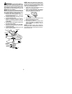
Shoulder s trap with warning
S
4--point weed blade
S
Trimmer head (assembled on unit)
S
Handlebar
S
Wing nut (screwed onto shield)
S
Container of oil
WARNING:
Always stop unit and dis-
connect spark plug before performing any as-
sembly procedures.
WARNING:
If received assembled,
repeat all steps to ensure your unit is properly
assembled and all fasteners are secure.
Examine parts for damage. Do not use dam-
aged parts.
NOTE:
If you need assistance or find parts
missing or damaged, call 1-800-554-6723.
It is normal for the fuel filter to rattle in the
empty fuel tank.
Finding fuel or oil residue on muffler is normal
due to carburetor adjustments and testing
done by the manufacturer.
TOOLS REQUIRED
S
2 hex wrenches (provided)
S
Adjustable wrench or large pliers
S
Phillips s crewdriver
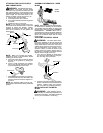
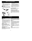
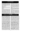
ATTACHING THE HANDLEBAR
DANGER:
During blade usage, the
barrier portion of the handlebar must be
installed as shown to provide a barrier be-
tween operator and the spinning blade.
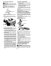
1. Locate the decal on the handlebar. This
decal includes two arrows. Position the
handlebar with the mounting bracket be-
tween these arrows.
2. Position t he bracket cover over the han-
dlebar. Again make sure the handlebar is
between the arrows.
3. Insert screws and hand tighten only. Be
sure the handlebar is installed correctly;
then, tighten eac h screw securely with
the short hex wrench.
Bracket Cover
Screw
Mounting
Bracket
Handlebar
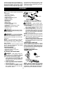
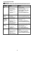
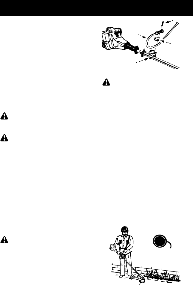
ASSEMBLY OF SHOULDER STRAP
WARNING:
Proper shoul der strap
and handlebar adjustments ar e required before
starting the engine.
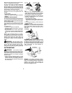
1. Tr y on shoulder strap and adjust for fit and
balance beforestarting theengine orbegin-
ning a cutting operation.
2. Insert your right arm and head through.
the shoulder strap and allow it to rest on
your left shoulder. Make sure the danger
sign is onyour back and the hookis tothe
right side of your waist.
NOTE:
A one-half twist is built in the shoulder
strap to allow the strap to rest flat on the shoul-
der.
3. Adjust the strap, allowing the hook to be
about 6 inches below the waist.
4. Fasten the s trap hook to the clamp located
between the trigger handle and the handle-
bar clamp base and lift the tool to the oper-
ating position.
CONFIGURING YOUR UNIT
Yo u c an configure your unit using a cutting
head for grass and light weeds, or a weed
blade for cutting grass, weeds, and brush up
to 1/2 inch in diameter. To assemble your unit,
go to the section for the desired configuration
and follow the instructions.
ASSEMBLY INFORMATION --
TRIMMER HEAD
TRIMMER
HEAD
NOTE:
Remove the b lade and metal s hield
before attaching the plastic shield and trimmer
head. R e fer to the sec tions ASSEM BLY IN-
FORMATION --WEED BL ADEandreve rs ethe
steps to remove the metal shield and blade.