


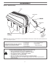

9
W
AR
N
I
NG
Do
n
o
t
o
p
e
r
a
t
e
m
o
w
e
r
u
n
l
e
s
s
c
o
n
t
a
i
n
e
r
i
s
p
r
o
p
e
r
l
y
i
s
n
s
t
a
l
l
e
d
.
Con
t
a
i
n
e
r
i
s
s
u
b
j
ec
t
t
o
w
e
a
r
a
n
d
d
e
t
i
e
ri
o
r
a
t
i
o
n
.
Ch
e
c
k
b
a
g
fr
e
q
u
e
n
t
l
y
.
Re
p
l
a
c
e
w
h
e
n
c
r
a
c
k
e
d
o
r
d
a
m
ag
e
d
.
Use
o
n
l
y
a
r
e
c
o
m
m
en
d
e
d
r
e
p
l
a
c
e
m
e
n
t
c
o
n
t
a
i
n
e
r
.
W
AR
N
I
NG
Do
n
o
t
o
p
e
r
a
t
e
m
o
w
e
r
u
n
l
e
s
s
c
o
n
t
a
i
n
e
r
i
s
p
r
o
p
e
r
l
y
i
s
n
s
t
a
l
l
e
d
.
Co
n
t
a
i
n
e
r
i
s
s
u
b
j
e
c
t
t
o
w
e
a
r
a
n
d
d
e
t
i
e
r
i
o
r
a
t
i
o
n
.
Ch
e
c
k
b
a
g
fr
e
q
u
e
n
t
l
y
.Re
p
l
a
c
e
w
h
e
n
c
r
a
c
k
e
d
o
r
d
a
m
a
g
e
d
.
Us
e
o
n
l
y
a
r
e
c
o
m
m
en
d
e
d
r
e
p
l
a
c
e
m
e
n
tc
o
n
t
a
i
n
e
r
.
0
2
0
8
3
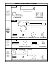
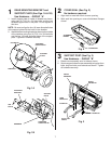
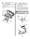
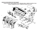
CONTAINER MOUNTING (See Fig. 6)
No hardware required
1. Install one container to left side fi rst with warning to
outside of unit. Install another container to center posi-
tion and one in right position.
NOTE: Right con tain er should always over lap left con tain er
at center supports.
2. Close cover and lock latch handles over center sup port
tubes.
6
Fig. 6
COVER LATCH
HANDLES
CONTAINER
WARNING
CONTAINER
HANDLE
CONTAINER
WARNING
CENTER
SUPPORT
TUBES
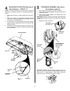
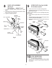
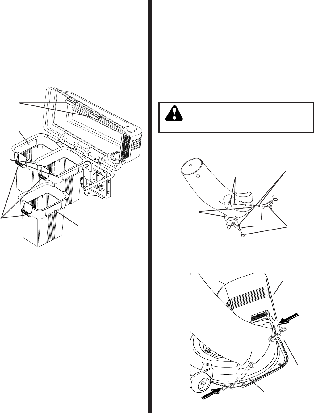
LOWER CHUTE (See Fig. 7A & 7B)
Use Hardware - - GROUP "D"
1. Press weld nut into rubber latch and install two latch
hook as sem blies to lower chute using screw, washer,
and lock washer as shown.
2. Tighten hard ware securely.
3. Raise and hold defl ector shield in upright position.
4. Place rear of chute over rear of mower deck opening.
Push chute down and forward to guide extended edge
of chute between discharge guard and mower deck.
5. Hook front latch into tab hole on front of mower deck.
6. Hook rear latch into fl ange hole on back of mower
deck.
7
CAUTION: Do not remove discharge guard
from mower. Raise and hold guard when
at tach ing lower chute and allow it to rest
on chute while in op er a tion.
Fig. 7A
02094
SCREW
WELD NUT
LATCH
WASHER
LOCK WASHER
REAR LATCH
FRONT
LATCH
DE FLEC TOR
SHIELD
Fig. 7B