


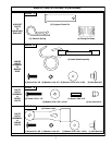
7
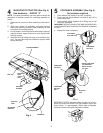
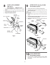
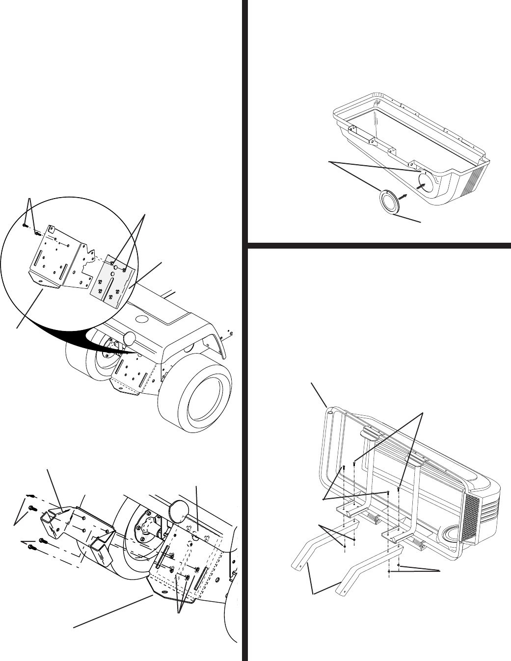
SUPPORT POST (See Fig. 3)
Use Hardware - - GROUP "B"
1. Rotate cover assembly onto its side as shown.
2. Secure support tubes to cover assembly using short hex
bolts, long hex bolts, and locknuts as shown. Tighten
all hardware securely.
02
0
8
6
02
35
7
1
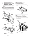
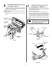
REAR MOUNTING BRACKET and
SUPPORT PLATE (See Figs. 1A & 1B)
Use Hardware - - GROUP "A"
1. Install support plate to inside of drawbar as shown,
using two (2) 7/16-14 x 3/4 hex bolts and the two
threaded upper holes in the plate. Do not tighten at
this time.
NOTE: Be sure to align the four (4) lower threaded holes
of the support plate with the holes in the drawbar.
2. Assemble the mounting bracket as shown to the out side
of the drawbar using four (4) 7/16-14 x 3/4 hex bolts
and the four (4) lower threaded holes of the support
plate. Tighten all hard ware securely.
Fig. 1B
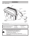
COVER SEAL (See Fig. 2)
No hardware required
1. Align mark on seal with mark at cover opening.
2. Work seal into opening so cover sits between fl anges
of seal.
2
3
ALIGNMENT
MARKS
COVER SEAL
Fig. 2
DRAWBAR
HEX BOLTS
THREADED
UPPER HOLES
SUPPORT
PLATE
Fig. 1A
HEX
BOLTS
SUPPORT
PLATE
DRAWBAR
THREADED
LOWER HOLES
MOUNTING
BRACKET
02356
LOCKNUTS
LOCKNUTS
SUPPORT
POSTS
LONG
HEX BOLTS
SHORT
HEX BOLTS
COVER
ASSEMBLY
Fig. 3