


11
OPERATION
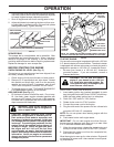
TO START ENGINE
Your snow thrower engine is equipped with both a 120 Volt
A.C. electric starter and a recoil starter. The electric starter
is equipped with a three-wire power cord and plug and is
designed to operate on 120 Volt A.C. household current.
• Be sure your house is a 120 Volt A.C. three-wire
ground ed system. If you are uncertain, consult a
li censed electrician.
WARNING: Do not use the electric
start er if your house is not a 120 Volt
A.C. three-wire grounded system. Se-
ri ous per son al injury or damage to your
snow thrower could result.
COLD START - ELECTRIC STARTER
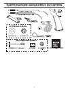
1. Insert safety ignition key (packed separately in parts
bag) into ignition slot until it clicks. DO NOT turn the key.
Keep the extra safety ignition key in a safe place.
2. Place ON / OFF switch in “ON” position.
3. Rotate choke control to “FULL” position.
4. Connect the power cord to the engine.
5. Plug the other end of the power cord into a three-hole
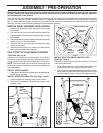
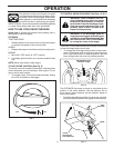
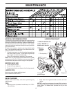
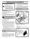
SKID PLATE
LOW POSITION (HIGH GROUND CLEAR ANCE)
HEX NUT
HIGH POSITION
(LOW GROUND
CLEARANCE)
AUGER
HOUSING
SCRAPER BAR
The scraper bar is not adjustable, but is reversible. After
con sid er able use it may become worn. When it has worn
almost to the edge of the housing, it can be reversed,
providing additional service before requiring replacement.
Replace a dam aged or worn scrap er bar.
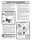
BEFORE STARTING THE ENGINE
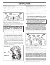
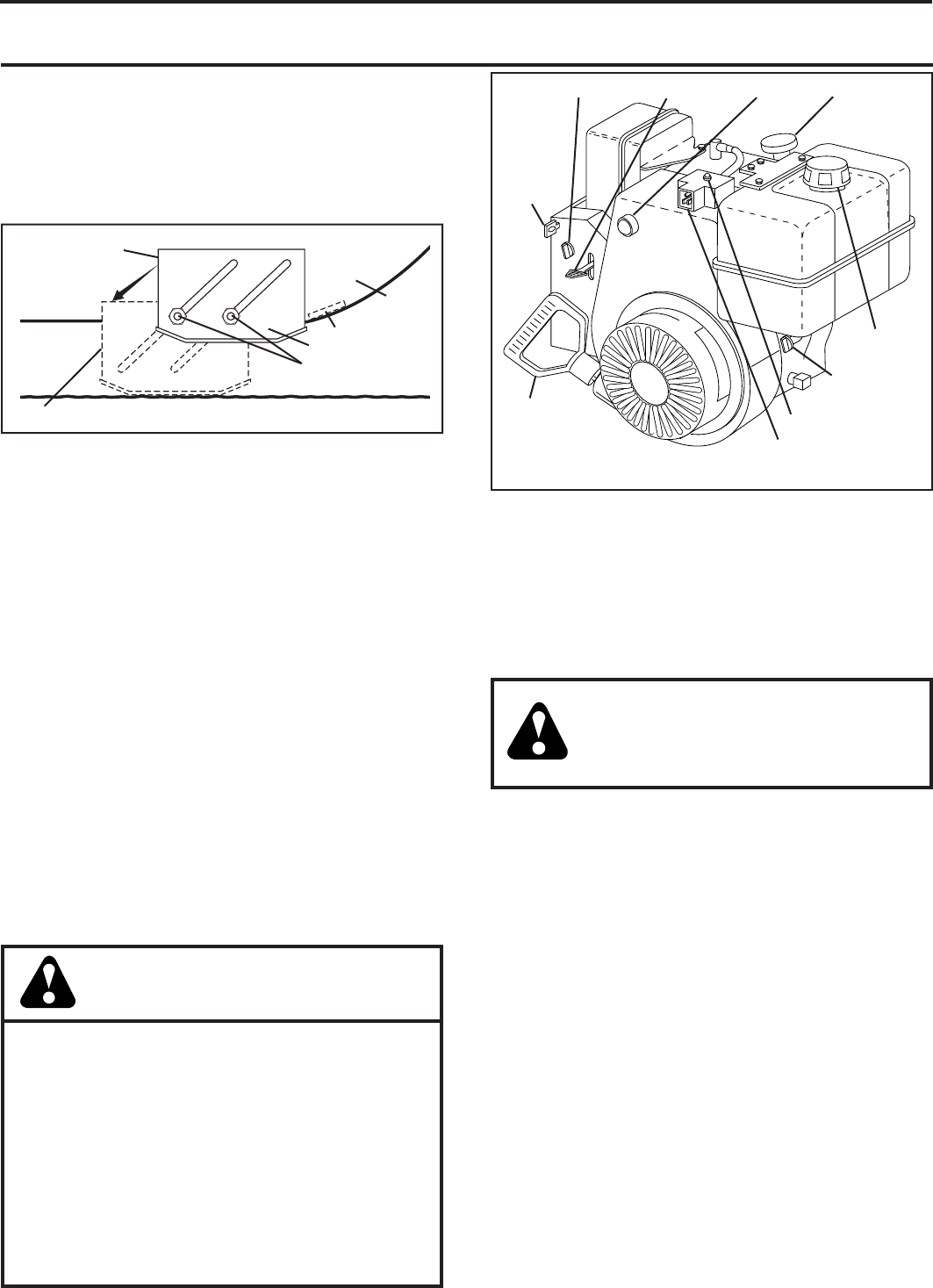
CHECK ENGINE OIL LEVEL (See Fig. 17)
The engine on your snow thrower has been shipped, from
the factory, already filled with oil.
1. Check engine oil with snow thrower on level ground.
2. Remove oil fill cap/dipstick and wipe clean, reinsert
the dipstick and screw tight, wait for a few seconds,
remove and read oil level. If necessary, add oil until
“FULL” mark on dipstick is reached. Do not overfill.
• To change engine oil, see “TO CHANGE ENGINE OIL”
in the Main te nance sec tion of this manual.
grounded 120 Volt A.C. receptacle.
NOTE: Do not use primer when start ing en gine with the
electric starter.
6. Push starter button until engine starts.
IMPORTANT: Do not crank engine more than five con-
tin u ous seconds between each time you try to start. Wait
5 to 10 seconds between each attempt.
7. When the engine starts, release the starter button and
slowly move the choke control to the “OFF” position.
8. Disconnect the power cord from the receptacle first,
then from the engine.
Allow the engine to warm up for a few minutes. Engine will
not develop full power until it has reached normal operat-
ing temperature.
FIG. 15
• If snow thrower must be operated over gravel surface,
use extra caution and be sure skid plates are adjusted
to lowest (highest scraper clear ance) position.
1. Shut off engine and wait for all moving parts to stop.
2. Adjust skid plates by loosening the hex nut, then mov-
ing skid plate to desired position. Be sure both plates
are adjusted evenly. Tighten securely.
ADD GASOLINE (See Fig. 17)
• Fill fuel tank to bottom of tank filler neck. Do not over-
fill. Use fresh, clean, regular unleaded gasoline with
a minimum of 87 octane. Do not mix oil with gasoline.
Purchase fuel in quan ti ties that can be used within 30
days to assure fuel freshness.
WARNING: Wipe off any spilled oil or
fuel. Do not store, spill or use gasoline
near an open flame.
CAUTION: Alcohol blended fuels (called
gas o hol or using ethanol or methanol) can at-
tract moisture which leads to separation and
for ma tion of acids dur ing storage. Acidic gas
can damage the fuel system of an engine while
in storage. To avoid engine problems, the fuel
system should be emptied be fore stor age of
30 days or longer. Empty the gas tank, start
the engine and let it run until the fuel lines
and carburetor are empty. Use fresh fuel next
season. See Storage In struc tions for ad di tion al
information. Never use engine or car bu re tor
cleaner products in the fuel tank or per ma nent
damage may occur.
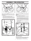
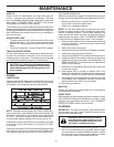
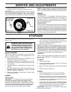
SCRAPER BAR
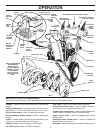
ENGINE OIL
FILL CAP /
DIPSTICK
FUEL SHUT-
OFF VALVE
PRIM ER
SAFETY
IG NI TION
KEY
THROT TLECHOKE CONTROL
STARTER BUTTON
RECOIL
STARTER
HANDLE
GAS O LINE
FILLER CAP
NOTE: ALL ITEMS ARE SHOWN IN THEIR TYPICAL LOCATION.
ACTUAL LOCATION MAY VARY WITH ENGINE ON YOUR UNIT.
POWER CORD PLUG
FIG. 22