


23
SERVICE AND ADJUSTMENTS
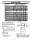
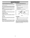
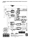
FIG. 23
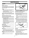
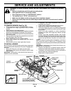
FIG. 24
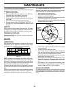
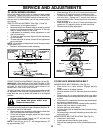
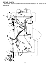
FIG. 25
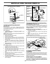
1-1/2"
JAM NUT
WITH PARKING BRAKE “ENGAGED”
OPERATING ARM
NUT “A”
STATIONARY
IDLER
TRANSAXLE
PULLEY
ELECTRIC
CLUTCH
CLUTCH ING
IDLER
CLUTCH LOCATOR
CLUTCH
WIRE
HAR NESS
TO REPLACE MOTION DRIVE BELT
(See Fig. 24)
Park the tractor on level surface. En gage parking brake.
For as sis tance, there is a belt installation guide decal on
bottom side of left footrest.
BELT REMOVAL -
• Remove mower (See “TO RE MOVE MOWER” in this
section of manual).
NOTE: Observe entire motion drive belt and position of all
belt guides and keepers.
• Disconnect clutch wire harness.
• Remove clutch locator.
• Remove belt from stationary idler and clutching idler.
• Remove belt downward from engine pulley and around
electric clutch.
• Pull belt slack toward rear of trac tor. Remove belt
up wards from transaxle pulley by de fl ect ing belt keep-
ers.
• Remove belt from center span keeper and pull belt
away from tractor.
BELT INSTALLATION -
• Carefully work new belt down be tween transaxle belt
keepers and onto the input pulley.
• Slide belt into the center span keeper.
• Pull belt toward front of tractor and roll belt around
electric clutch and onto engine pulley.
• Install belt through stationary idler and clutch ing
idler.
• Reinstall clutch locator and tighten nut securely.
• Reconnect clutch harness.
• Make sure belt is in all pulley grooves and in side all
belt guides and keep ers.
• Install mower (See “TO IN STALL MOWER” in this sec-
tion of manual).
CENTER SPAN
KEEPER
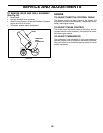
ADJUSTMENT
BOLT
NEUTRAL
LOCK GATE
GEARSHIFT LEVER
TRANSAXLE GEAR SHIFT LEVER NEU TRAL-
ADJUSTMENT (See Fig. 25)
The transaxle should be in neutral when the gear shift
lever is in neutral (N) (lock gate) position. The adjustment
is preset at the factory; however, if adjustment is needed,
proceed as follows:
• Make sure transaxle is in neutral (N).
NOTE: When the tractor rear wheels move freely, the
transaxle is in neutral.
• Loosen adjustment bolt in front of the right rear
wheel.
• Position the gear shift lever in the neutral (N) posi-
tion.
• Tighten adjustment bolt securely.
NOTE: If additional clearance is needed to get to ad just ment
bolt, move mower deck height to the lowest position.
TO AD JUST STEER ING WHEEL
ALIGN MENT
If steering wheel crossbars are not horizontal (left to right)
when wheels are positioned straight forward, remove steer-
ing wheel and reassemble per instructions in the Assembly
section of this manual.
FRONT WHEEL TOE-IN/CAMBER
The front wheel toe-in and camber are not adjustable on
your tractor. If damage has occurred to affect the front
wheel toe-in or camber, contact your nearest authorized
service center/department.