


22
SERVICE AND ADJUSTMENTS
FIG. 21
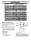
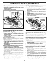
TO REPLACE MOWER BLADE (SEC OND ARY)
DRIVE BELT (See Fig. 22)
Park the tractor on level surface. En gage parking brake.
• Remove mower (See “TO REMOVE MOWER” in this
section of manual).
• Remove screws from R.H. and L.H. mandrel covers
and re move covers.
REMOVE MOWER DRIVE BELT
(Refer to “TO REMOVE MOWER DRIVE BELT” il lus tra tion
in this section of manual).
• Carefully roll belt over the top of R.H. mandrel pulley.
• Remove belt from idler pulleys.
• Check primary idler arm and two idlers to see that they
rotate freely.
• Be sure spring is securely hooked to primary idler arm
and spring arm.
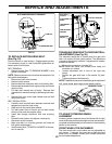
REMOVE MOWER BLADE (SECONDARY) DRIVE BELT
• Carefully roll belt off L.H. mandrel pulley.
• Remove belt from center mandrel pulley, idler pulley,
and R.H. man drel pulley.
• Remove any dirt or grass which may have ac cu mu lat ed
around mandrels and entire upper deck surface.
• Check secondary idler arm and idler pulley to see that
they rotate freely.
• Be sure spring is hooked in sec ond ary idler arm and
secondary spring arm.
INSTALL NEW MOWER BLADE (SECONDARY) DRIVE
BELT
• Install new belt in lower groove of R.H. mandrel pulley,
idler pulley, and center mandrel pulley as shown.
• Carefully roll belt over L.H. mandrel pulley. Make sure
belt is in all grooves properly.
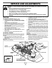
FIG. 22
L.H. MANDREL
IDLER
PUL LEY
CEN TER
MAN DREL
SPRING
SEC OND ARY
IDLER ARM
SEC OND ARY
SPRING ARM
R.H. MAN DREL
• Carefully check belt routing making sure belt is in the
grooves correctly.
• Reconnect R.H. suspension arm to rear deck bracket
with retainer spring.
• Reassemble R.H. mandrel cover.
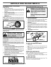
PRI MA RY
IDLER ARM
R.H. MANDREL
IDLER
PUL LEYS
ELEC TRIC
CLUTCH
PUL LEY
SPRING
ARM
RH MAN DREL
COVER
RH SUS PEN SION ARM
REINSTALL MOWER DRIVE BELT
(Refer to “TO REMOVE MOWER DRIVE BELT” illustration
in this section of man u al).
• Install belt into upper groove of R.H. mandrel pulley
and around both idlers. Pull belt to front of mower to
remove slack.
• Reinstall mandrel covers and se cure ly tighten all
screws.
• Carefully check belt routing making sure belt is in all
grooves correctly.
• Reinstall mower to tractor (See “TO INSTALL MOWER”
in this section of manual).
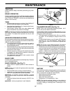
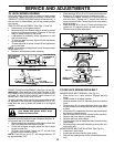
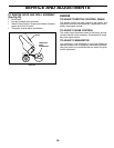
TO CHECK AND ADJUST BRAKE (See Fig.
23)
Your tractor is equipped with an ad just able brake system
which is mounted on the right side of the transaxle.
If tractor requires more than fi ve (5) feet to stop at highest
speed in high est gear on a level, dry concrete or paved
surface, then brake must be checked and ad just ed.
TO CHECK BRAKE
• Park tractor on a level, dry concrete or paved surface,
depress clutch/brake pedal all the way down and en-
gage parking brake.
• Place gear shift lever in neutral (N) position.
The rear wheels must lock and skid when you try to manually
push the tractor forward. If the rear wheels rotate, the brake
needs to be adjusted or the pads need to be replaced.
TO ADJUST BRAKE
• Depress clutch/brake pedal all the way down and en-
gage parking brake.
• Measure distance between brake operating arm and
nut “A” on brake rod.
• If distance is other than 1-1/2", loos en jam nut and turn
nut “A” until dis tance becomes 1-1/2". Re tight en jam
nut against nut “A”.
• Road test tractor for proper stopping distance as stated
above. Readjust if nec es sary. If stopping distance is
still greater than fi ve (5) feet in high est gear, further
main te nance is nec es sary. Replace brake pads or
contact a qualifi ed service center.