


6
SPECIAL NOTICE: This unit is equipped
with a temperature limiting muffler and spark
arresting screen which meets the require-
ments o fCalifornia Codes 4442and4443. All
U.S. forest land and the states of California,
Idaho, Maine, M innesota, New Jersey , Ore-
gon, and Washington require by law that
many internal combustion engines be
equippedwithasparkarrestingscreen. Ifyou
operateinalocalewheresuch regulationsex-
ist, youare legallyresponsibleformaintaining
theoperatingconditionof theseparts. Failure
to do so is a violation of the law. For normal
homeowner use,the mu fflerandsparkarrest-
ing screen will not require any service. After
50 hours of use, we recommend that your
mufflerbeservicedorreplacedby yourautho-
rized service dealer.
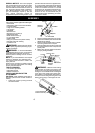
ASSEMBLY
CARTON CONTENTS
Check carto n contents against t he foll owinglist:
S Powerhead
S Attachment (with trimm er head installed)
S Cupped washer
S Large nut for installing blades
S Hex wrench
S Handlebar
S Bracket cover
S Bracket cover screws (2)
S Metal blade shield
S Blade shield screws (4)
S 4--point weed blade
S Plastic shield
S Wing nut (screwed onto plastic shield)
S Shoulder strap with warning
S Container of oil
WARNING: Alwaysstopunit anddis-
connectspark plugbefore performinganyas-
sembly procedures.
WARNING: If received assembled,
repeat allsteps toensure your unit isproperly
assembled and all fasteners are secure.
Examine parts for damage. Do not use dam-
aged parts.
NOTE: If you need assistance or find parts
missing or damaged, call 1-800-554-6723.
It is normal for the fuel filter to rattle in the
empty fuel tank.
Finding fuelor oil residue on muffler isnormal
due to carburetor adjustments and testing
done by the m anufacturer.
TOOLS REQUIRED
S Hex wrench (provided)
S Adjustable wrench
S Phillips screwdriver
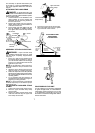
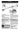
INSTALLING BRUSHCUTTER
ATTACHMENT
CAUTION:
When installing brushcutter at-
tachment, place the unit on a flat surface fo r
stability.
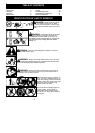
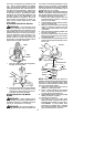
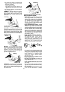
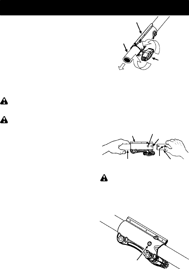
1. Loosen the coupler by turning the knob
counterclockwise.
Shipping
protector
Coupler
Knob
LOOSEN
TIGHTEN
2. Remove shipping protector fromcoupler .
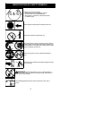
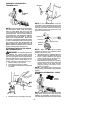
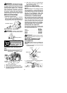
3. Remove the shaft cap from thebrushcutter
attachment (if present).
4. Position locking/release button ofattach-
ment into guide recess of coupler.
5. Pushthe a ttachmentintothe coupleruntil
the locking/release button snaps into the
primary hole.
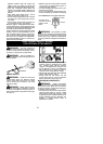
6. Before using the unit, tighten the knob se-
curely by turning clockwise.
Coupler
Primary Hole
Upper
Shaft
Locking/
Release
Button
Attachment
Guide Recess
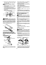
WARNING: Make sure the locking/
release button is locked in the primary hole
and theknob is securely tightened before op-
erating the unit.Allattachments aredesigned
to be used in the primary hole unless other-
wise stated in the applicable attachment in-
struction manual. Using the wrong holecould
lead to serious injury or damage to the unit.
Locking/Release
Button in Primary Hole