


6
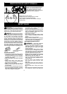
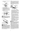
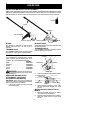
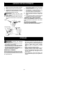
Spacer Tabs
LOWER SHOUL DE R ST RAP
CLAMP
Spacer Tabs
positioned for use
on 1″ (2.5 cm)
diameter
upper shaft
1. Place the upper shoulder strap clamp
overtheuppershaftabove thehandlebar.
2. Position the lower shoulder strap clamp
under the upper shaft and align theupper
andlowerclampscrew holes(usespacer
tabs between upper and lower clamps if
necessary tosecureclamp, i.e.for 1″(2.5
cm) diameter upper shaft).
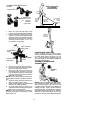
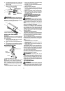
Upper Shoulder
Strap C lamp
Screws
Lower Shoulder
Strap C lamp
POWERHEAD
END
ATTACHMENT
END
3. Insert two screws into the screw holes.
4. Secure shoulder strap clamp by tighten-
ing screws with the hex wrench.
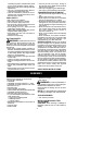
5. Insert your right arm and head through
the shoulder strap and allow it to rest on
your left shoulder . Make sure the danger
sign is onyourback andthe hook is tothe
right side of your waist.
NOTE:A one-half twistis builtin theshoulder
strapto allowthestrap torestflaton theshoul-
der.
6. Adjust the strap, allowing the hook to be
about 6 inches below the waist.
7. Fasten the strap hook to th e clamp and lift
the tool to the operating position.
8. Try on shoulder strap and adjust for fit
and balance before starting the engine or
beginning a cutting operation .
NOTE: It may be necessary to relocate the
shoulder strap clamp on the shaft for proper
balancing of unit.
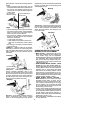
SHOULDER STRAP
ADJUSTMENT
FOR BALANCE
6 inches
(15 cm)
below
waist
30 inches
(76 cm)
minimum
4 -- 12 inches
(10 -- 30 cm)
above
ground
30 inches
(76 cm)
minimum
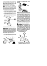
CONFIGURING YOUR UNIT
You can configure your unit using a trimmer
head for grass and light weeds, or a weed blade
for cutting grass, weeds, and brush up to 1/2
inch (1 cm) in diameter . To assemble your unit,
go to the section for the desired configuration
and follow the instructions.
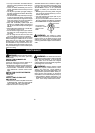
ASSEMBLY INFORMATION --
TRIMMER HE AD
TRIMMER
HEAD
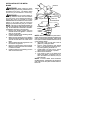
NOTE: Remove theblade andmetal shield be-
fore attaching the plastic shield and trimmer
head. To remove blade, align hole in the dust
cup with the hole in theside of the gearbox by
rotating the blade. Insert a small screwdriver
into aligned holes. This wi ll keepthesha ft f rom
turning while loosening the blade nut. Remove
blade nut by turning clockwise. Remove the
screwdriver. Remo ve both washers and bla de.