


5
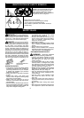
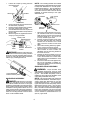
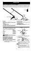
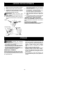
1. Loosen the coupler by turning the knob
counterclockwise.
Attachment
Coupler
Knob
LOOSEN
TIGHTEN
2. Remove the shaft cap from the brushcut-
ter attachment (if present).
3. Position locking/release button of attach-
ment into guide recess of coupler.
4. Push theattachment intothe coupleruntil
the locking/release button snaps into the
primary hole.
5. Before using theunit, tightentheknobse-
curely by turning clockwise.
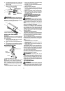
Coupler
Primary Hole
Upper
Shaft
Locking/
Release
Button
Attachment
Guide Recess
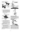
WARNING: Make sure the locking/re-
lease button is locked i n the prim ary hole and
the knob is securely tightened before operat-
ing the unit. Using the wrong hole could lead to
serious injury o r damag e to the unit.
Locking/Release
Button in Primary Hole
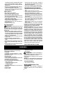
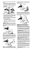
HANDLEBAR ASSEMBLY
DANGER:RISKOFCUT. Toavoidse-
rious injury, the barrier portion of the handle-
bar must be installed as shown on the upper
shaft of thepowerheadto provide abarrier be-
tweenoperator andthespinningblade. Attach
handlebar mounting bracket above arrow o n
safety warning decal on the upper shaft(pow-
erheadend ofunit). Ensurehandlebar is posi-
tioned on mounting bracket a t the end of the
arrow on the handlebar decal.
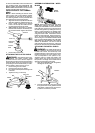
NOTE: T wo mounting brackets are included
with this attachment. Both brackets are provided
to adapt this attachment for use with power-
heads that have either a 1″ (2.5 cm) diameter or
a7/8″ (2.2 cm) d iameter upper shaft. The cor-
rect bracket must be used to ensure that the
handlebar is mounted securely to the upper
shaft before use.
Screw
Mounting
Bracket
Handlebar
Bracket Cover
1. Place the mounting bracket over the up-
per shaft above the arrow on the safety
label.Besuretousethecorrectmounting
bracket for either the 1″ (2.5 cm) or 7/8″
(2.2 cm) diameter upper shaft.
2. Position one of the bracket covers under
the upper shaft and align the mounting
bracket and the bracket cover screw
holes. Insert two screws into the screw
holes.
3. Secure the mounting bracket by tighten-
ing the screws with the hex wrench.
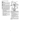
4. Locate the decal on the handlebar. This
decal includes an arrow. Position the
handlebar with the mounting bracket at
the end of the arrow .
5. Position the second bracket cover over
the handlebar. Align the mounting brack-
et and the bracket cover screw holes.
Again make sure the handlebar is at the
end of the a rrow.
6. Insert two screws and hand tighten only.
Be sure the handlebar is installed cor-
rectly; then, tighten each screw securely
with the hex wrench.
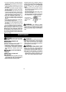
SHOULDER STRAP ASSEMBLY
WARNING: Proper shoulder strap
and handlebar adjustments must be made
with theengine completely stoppedbeforeus-
ing unit. The sho ulder strap cla mp must be
installed as shown above the handlebar on the
upper shaft (powerhead end of unit).
NOTE: The lower shoulder strap clamp has
twospacertabs attached. Thesetabs arepro-
vided to adapt this attachment for use with
powerheads that have a 1″ (2.5 cm)diameter
upper shaft (the shoulder strap clamp will not
tightendownsecurely onthe1″(2.5cm)diam-
eter upper shaft without using these spacer
tabs). Thetabs mustbe broken offcompletely
before use and placed over the screw holes
onthe lowershoulderstrapclamp.Thesetabs
are not needed for powerheads with a 7/8″
(2.2 cm) upper shaft.