


12
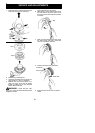
4. Pull starter rope handle sharply until en-
gine starts and runs.
5. Allow unit to run for 10--15 seconds, then
fully squeeze the throttle trigger to disen-
gage the starting system.
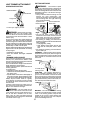
STARTING A WARM ENGINE
1. Squeeze and hold the throttle trigger.
Keep throttle trigger fully squeezed until
engine runs smoothly.
2. Pull starter ropesharply whilesqueezing
throttle trigger until engine runs.
NOTE:Normally, the warm starting procedure
can be used within 5--10 minutes after the unitis
turned off. If the unit sits for more than 10 min-
utes without being ran, it will be necessary to
start the unit by following the steps under
STARTINGACOLDENGINEorfollowingthe
starting instruction steps shown on the unit.
START ING A FLOODED ENGINE
Flooded engines can be started by placing
the start lever to the RUN position. Fully
squeeze throttle trigger. Pull the starter han-
dlerepeatedly whilesqueezing throttletrigger
until engine starts and runs. This could re-
quire pulling the starter handle many times,
depending on how badly the unit is flooded.
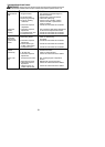
If the unit still doesn’t start, refer to
TROUBLESHOOTING TABLE or call
1-800-554-6723.
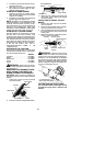
OPERATING THE COUPLER
This model is equipped with a coupler which
enables optional attachments to be installed.
The optional attachments are:
MODEL:
Cultivator PP2000T...................
Blower PP3000B.....................
Brushcutter PP4000C.................
Pruner PP5000P.....................
Pruner PP5500P.....................
WARNING: Alwaysstopunit anddis-
connect spark plugbeforeremoving orinstal-
ling a ttachments.
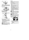
REMOVING LINE TRIMMER ATTACH-
MENT, EDGER ATTACHMENT OR
OTHER OPTIONAL ATTACHMENTS
CAUTION:
When removing orinstalling at-
tachments, place the uniton a flat surface fo r
stability.
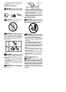
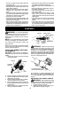
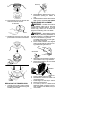
1. Loosen the coupler by tu rning the knob
counterclockwise.
Coupler
Knob
LOOSEN
TIGHTEN
Upper Shaft
Attachment
2. Press and hold the locking/release button.
L
ocking
/
Release
Button
Coupler
Upper Shaft
Attachment
3. While securely holding the engine and
upper shaft, pull the a ttachment straight
out of the coupler.
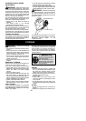
INSTALLING OPTIONAL ATTACH-
MENTS
1. Remove the shaft cap from the attach-
ment (if p resent).
2. Positionlocking/release buttonofattach-
ment into guide recess of coupler .
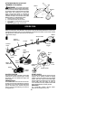
3. Pushtheattachmentintothecoupleruntil
the locking/release button snaps into the
primary hole.
4. Beforeusingtheunit, t ightentheknobse-
curely by turning clockwise.
Coupler Primary Hole
Upper
Shaft
Locking/
Release
Button
Attachment
Guide Recess
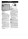
WARNING: Make sure the locking/
release button i s locked in the primary hole
and theknob is securely tightened beforeop-
erating the unit. Al l atta chment s are des igned
to be used in the primary hole unless otherwise
stated in the applicable attachment instruction
manual. Usingthe wrong holecouldlead toseri-
ous injury or dam age to the unit.
Locking/Release
Button in Primary Hole
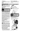
OPERATING INSTRUCTIONS
It is recommended that the engine not be
operated for longer than 1 minute at full
throttle.