


-- 3 --
D Disconnect spark plug before performing
maintenance except for carburetor adjust-
ments.
D Use only recommended Poulan PRO re-
placement parts; use of any other parts
may voidyour warranty and causedamage
to your unit.
D Empty f uel tank before storing the unit. Use
upfuelleftin carburetor by starting engine and
letting it run until it stops.
D Do not use any accessory or atta chment
other than those recommended by manufac-
turer for use with your unit.
D Do not store the unit or fue l ina closedarea
where fuel vapors can reach sparks or an
open flame from hot water heaters, electric
motors or switches, furnaces, etc.
D Store in a dry area out of reach of children.
SPECIAL NOTICE: This unit is equipped
with a temperature limiting muffler and spark
arresting screen which meets the require-
ments of California Codes 4442 and 4443.All
U.S. forest land and the states of California,
Idaho, Maine, Minnesota, New Jersey, Ore-
gon, and Washington require by law that
many internal combustion engines be
equippedwithaspark arresting screen. Ifyou
operateinalocalewheresuch regulationsex-
ist, you arelegally responsiblefor m aintaining
the operatingconditionof theseparts. Failure
to do so is a violation of the law. Refer to the
MAINTENANCE section for information on
maintenance of t he muffler and spark arrest-
ing screen.
SAFETY NOTICE: Exposure to vibrations
through prolonged use of gasoline powered
hand tools could cause bloodvessel or nerve
damage in the fingers, h ands, and joints of
people prone t o circulation disorders or ab-
normal swelling. Prolonged use in cold
weather h asbeenlinked toblood vesseldam-
age in otherwise healthy people.Ifsymptoms
occur such as numbness, pain, loss of
strength, change in skin color or texture, or
loss of feeling in the fingers, hands, or joints,
discontinue the use of this tool and seek
medical attention. An antivibration system
does not guarantee the avoidance o f these
problems. Users who operate power tools on
a continual and regular basis must monitor
closely their physicalcondition andthe condi-
tion of this tool.
ASSEMBLY
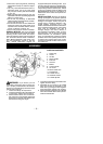
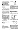
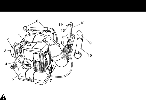
CARTON CONT ENTS
1. Spark plug
2. Choke
3. Air filter
4. Starter handle
5. Fuel tank
6. Harness
7. Muffler
8. Control handle
9. Air nozzle
10. Blower outlet tube
11. Flexible tube
12. Throttle control
13. ON/STOP switch
14. Throttle adjuster
WARNING: If you receive your unit
assembled, check each step to insure your
unit is properly assembled and all fasteners
are secure.Follow allsafetyinformation inthe
manual and on the unit.
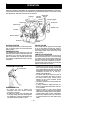
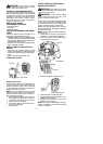
1. Locate and identify all components.
2. Connect theflexibletube totheoutlettube
on the engine. Tighten the hose clamp.
3. Remove bottom screw from control han-
dle. Install the control handle against the
flared area on the base tube with the ON/
STOP switch facing the engine.
4. Connectthebasetubeto theflexibletube.
Tighten the hose clamp.
5. Assemble the air nozzle to the middle
tube and connect the assembly to the
base tube by pushing the t ubes together
and turning them until they lock in place.
6. Remove throttle cable clamp fromflexible
tube. Place throttle cable in clamp andre-
install on flexible tube.