


13
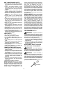
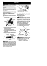
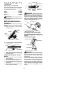
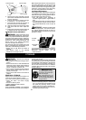
Hub
Line in Notch
Line in Notch
L
ine exit holes
5. Wind the line evenly and tightly onto the
spool. Wind inthe direction of the arrows
found on the spool.
6. Push the lines intothe notches, leaving 3
to 5 inches (7 -- 12 cm) unwound.
7. Insert the lines into the the exit holes in
the hub as shown in the illustration.
8. Align the notches with the line exit holes.
9. Push spool into hub until it snaps into
place.
10. Pull t helines extendingoutsideofthehub
to release the lines from the notches.
CARBURETOR ADJUSTMENT
WARNING: Keep ot hers away when
making idle speed adjustments. The trimmer
head or any optional attachment will be spin-
ningduringmostofthis procedure. Wearyour
protective equipme nt and observe all safety
precautions. After m aking adjustments, the
trimmer head or any optional attachment
must not move/spin at idle speed.
The carburetor has been carefully set at the
factory.Adjustments may benecessary ifyou
notice any of the following conditions:
S Engine will not idle when the throttle is
released.
S The trimmer head or any optional
attachment moves/spins at idle.
Make adjustments with the unit supported so
the cutting attachment is off the ground and
will not make contact with any object. Hold
theunit byhand whilerunningand makingad-
justments. Keep all parts of your body away
from the cutting attachment and muffler.
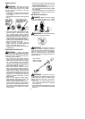
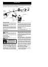
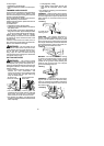
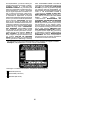
Idle Speed Adjustment
Allow enginetoidle. Adjustspeed untilengine
runs without trimmer head or any optional at-
tachment moving or spinning (idle too f ast) or
engine stalling (idle speed too slow).
S Turn idle speed screw clockwise to
increase engine speed if engine stalls or
dies.
S Turn idle speed screw counterclockwise to
decrease engine speed if trimmer head or
any optional attachment moves or spins at
idle.
WARNING: Recheck the idle speed
after each adjustment. T he trimmer head or
any optional attachment must not move or
spin atidlespeedtoavoid seriousinjury tothe
operator or others.
Idle Speed
Screw
Air Filter
Cover
If yourequire furtherassistanceorareunsure
about performing this procedure, contact an
authorized service dealer or call
1--800--554--6723.
STORAGE
WARNING: Perform the following
steps after each use:
S Allow enginetocool beforestoring ortrans-
porting.
S Store unit and fuel in a well ventilated area
where fuel vapors cannot reach sparks or
open flames from water heaters, electric
motors or switches, furnaces, e tc.
S Store unit with all guards in place. Position
unit so that any sharp object cannot acci-
dentally cause injury .
S Store unit and fuel well out of the reach of
children.
SEASONAL STORAGE
Prepare unitfor storage atend of season orif
it will not be used for 30 days or more.
If your unit is to be stored for a period of time:
S Clean the entire unit before lengthy
storage.
S Store in a clean dry area.
S Lightly oil external metal surfaces.
FUEL SYSTEM
Under FUELING ENGINE in the OPERA-
TION sectionof thismanual,seemessagela-
beled IMPORTANT regarding the use of ga-
sohol in your engine.
Fuel stabilizer is an acceptable alternative in
minimizing the formation offuel gumdeposits
during storage. Add stabilizer to the gasoline
in the fuel tank or fuel storage container. Fol-
low the mix instructions found on stabilizer
container. Runengine at least 5minutes after
adding stabilizer.
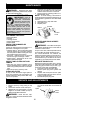
HELPFUL TIP
During storage of yourgas/
oilmixture, theoil will sepa-
rate from the gas.
We recommend that you
shake the gas can weekly
toinsure p roper blendingof
the gas and oil.
ENGINE
S Remove spark plugand pour1 teaspoon of
40:1,2-cycleengine oil(air cooled) through
the spark plug opening. Slowly pull the
starter rope 8 to 10 times to distribute oil.
S Replace spark plugwith newone ofrecom-
mended type and heat range.