14
Cleaning the air filter:
A dirty air filter decreases engine perform-
ance and increases f ue l consumption and
harmful emissions. Always clean after 10
tanks of fuel or 5 hours of operation, which-
ever comes first. Clean more frequently in
dusty conditions. Ausedairefiltercannever
be completely cleaned. It is advisable tore-
placeyourairfilterwithanewoneafterevery
50hoursofoperation,orannually,whichever
comes first.
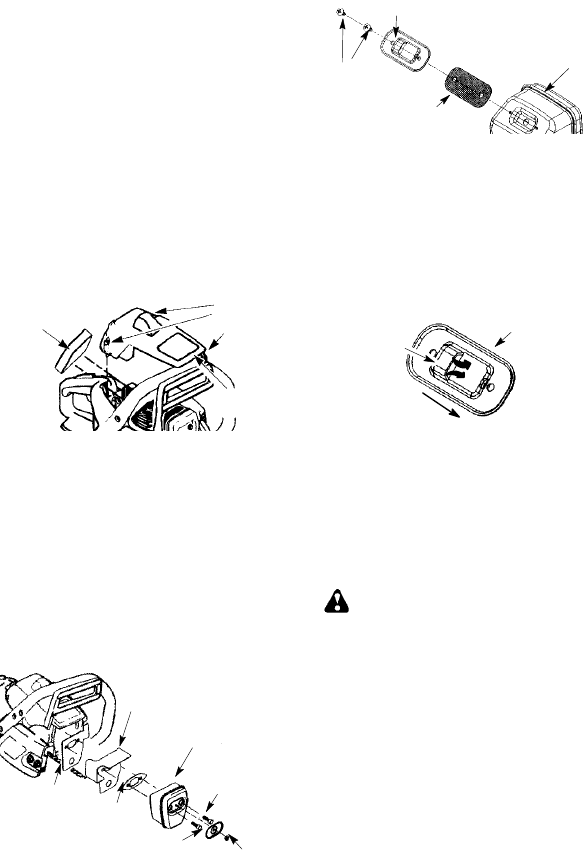
1. Loosen 3 screws o n cylinder cover.
2. Remove cylinder cover.
3. Remove air filter.
4. Cleanthe airfilter usinghotsoapywater.
Rinsewithcleancoolwater. Airdrycom-
pletely before reinstalling.
5. Lightly oilair filter before installing to im-
prove the efficiency of air filter. Use
2--cycle engineoil or motoroil (SAE30).
Squeeze excess oil from filter.
6. Reinstall air filter.
7. Reinstall cylinder cover and 3 screws.
TIghten securely.
Air Filter
Cylinder
Cover
Screws
Cylinder
Cover
INSPECT MUFFLER AND SPARK
ARRESTING SCREEN
As theunit is used, carbon deposits buildup
on the muffler and spark arresting screen,
andmustberemovedtoavoidcreating afire
hazard or affecting engine performance.
Replacethespark arrestingscreenifbreaks
occur.
CLEANING THE SPARK ARREST-
ING SCREEN
Cleaning is required every 25 hours of op-
eration or annually, whichever comes first.
Muffler
Gasket
Muffler
Bolts
Muffler
L
ocknut
Outlet
Guide
Bolt Cover
Backplate
1. Loosenand removethe locknut fromthe
bolt cover.
2. Remove the bolt cover.
3. Loosen and remove the 2 muffler bolts.
Remove themuffler, muffler gasket,out-
let guide and backplate. Notice the ori-
entationof theseparts forreassembling.
4. Locate the 2 outlet cover screws on the
muffler. Loosen and remove both
screws.
5. Remove the outlet cover.
BACK VIEW OF
MUFFLER
Muffler
Spark Arresting
Screen
Outlet Cover
Screws
6. Remove spark arresting screen.
7. Clean the spark arresting screen with a
wirebrush.Replacescreenifany wiresare
broken or screen is blocked after cleaning.
8. Reinstall spark arresting screen.
9. Reinstall outletcoverand 2screws. En-
sureoutletcoverandbothscrewsarere-
installed correctly (see illustrations) to
prevent damage to t he saw. The ex-
haust outlet must face the chain brake
(bar side) of the saw.
Exhaust Outlet must face chain
brake (bar side) of chain saw
Outlet Co
v
er
Exhaust
Outlet
10. Inspect the muf fler gasket and replace if
damaged.
11. Reinstall backplate, outlet guide, muf fler
gasket, and muffler using muffler bolts.
Tighten until secure.
12. Reinstallboltcover andlocknut. Tighten
securely.
CARBURET OR A DJUSTMENT
WARNING: The chain will bemov-
ingduring mostofthis procedure. Wearyour
protective equipment andobserve all safety
precautions.Thechainmustnotmoveatidle
speed.
The carburetor has been carefully set at the
factory . Adjustments may be necessary if
you notice any of the following conditions:
S Chainmoves at idle.See IDLE SPEED--T
adjusting procedure.
S Sawwill notidle.See IDLESPEED--T ad-
justing procedure.
Idle Speed--T
Allow engine to idle. If the chain moves, idle
istoofast. Iftheenginestalls,idleistooslow .
Adjustspeeduntil engineruns withoutchain
movement (idle too fast) or stalling (idle too
slow). Theidle speedscrewis locatedinthe
area above the primer bulb and is labeled T.
S Turn idlespeed screw (T) clockwise to in-
crease engine speed.
S Turn idle speed screw (T) counterclock-
wise to decrease engine speed.
If you require further assistance or are unsure
about performing this procedure, contact your


