


6
damage in otherwise healthy people. If
symptoms occur such as numbness, pain,
loss of strength,changeinskincolor ortexture,
or loss of feelingin the fingers,hands, or joints,
discontinue the use of this tool and seek
medical attention. An anti-vibration system
does not guarantee the avoidance of these
problems. Users who operate power tools on
a continual and regular basis must monitor
closely t heir physical condition and the
condition of this tool.
SPECIALNOTICE:Yoursawisequipped
with atemperaturelimiting mufflerandspark
arresting screen which meets the
requirements of California Codes 4442 and
4443. All U.S. forest land and the states of
California, Idaho, Maine, Minnesota, New
Jersey, Oregon, and Washington require by
law that many internal combustion engines
tobeequippedwithasparkarrestingscreen.
Ifyouoperateachainsawinastateorlocale
wheresuchregulations exist,youarelegally
responsible for maintaining the operating
condition of these parts. Failure to do so is
aviolationof thelaw . Refer tothe SERVICE
section for maintenance of the spark
arresting screen.
FailuretofollowallSafetyRules andPrecau-
tionscanresult inserious injury. Ifsituations
occur which are not covered in this manual,
use care and good judgement. If you need
assistance, contact your authorized service
dealer or call 1-800--554--6723.
STANDARDS: This saw is listed byUnder-
writer’s Laboratories, Inc., in accordance with:
ANSI B175.1--2000 American National
Standards for Gasoline--Powered Chain
Saws -- Safety Requirements
CSA Z62.1--03 Chain Saws -- Occupational
Health and Safety
CSA Z62.3--96 Chain Saw Kickback Occu-
pational Health and Safety
ASSEMBLY
Protective gloves (not provided) should be
worn during assembly.
ATTACHINGTHEBAR&CHAIN(Ifnot
already attached)
WARNING: If receive d assemb led ,
repeat all steps to ensure your saw is properly
assembled and all fasteners are secure. Al-
ways wear gloves when handling the chain.
Thechain issharp and can cut you even when
it is not moving!
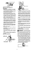
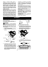
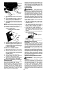
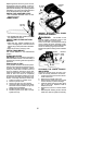
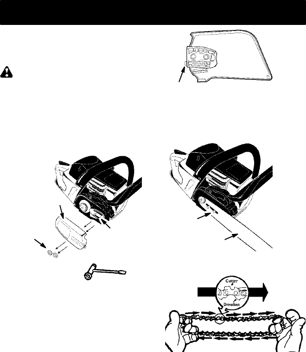
1. Loosenandremovethebarnuts andthe
clutch cover from the saw.
2. Remove the plastic shipping spacer (if
present).
Clutch cover
Bar nuts
Chain adjustment tool
(Bar Tool)
Location of
shipping
spacer
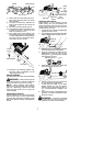
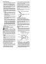
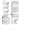
3. An adjustingpi nan dscrewis used toad-
just the tension of t he chain. It is very im-
portant when assembling the bar , that the
pin located on the adjusting screw aligns
intoaholeinthebar .Turningthescrewwill
move the adjustment pin up anddown the
screw . Locate this adjustment before you
begin mounting the bar onto the saw . See
following illustration.
Adjustment located on clutch cover
Inside
view of
clutch
cover
4. Turn the adjusting screw by hand coun-
terclockwise until the adjusting pin just
touches the stop. This should allow the
pin to be near the correct position.
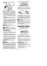
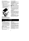
5. Slideguide baron barbolts until guidebar
stops against clutch drum sprocket.
Guide bar
Bar bolts
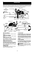
6. Carefully remove the chainfrom thepack-
age. Hold chain with the drive links as
shown.
CUTTERS MUST FACE IN
DIIRECTION OF ROT
A
TION
Tip of
Bar