5
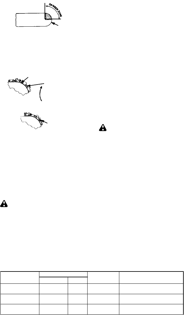
Symmetrical Guide Bar
Large Radius Tip
S Low--Kickback Chain, designed with a
contoured depth gauge and guard link
which deflect kickback force and allow
wood t ogradually rideintothecutter.Low--
Kickback Chain has met kickback per-
formance requirements when tested on a
representative sample of chain saws be-
low 3.8 cubic inch displacement specified
in ANSI B175.1.
Low--- Kickback
Chain
Not a Low--- Kickback Chain
Can ObstructMaterial
Contoured Depth Gauge
Elongated Guard Link
Deflects
kickback force
and allows wood
to gradually ride
into cutter
S Front Hand Guard, designed to reduce the
chance of your left hand contacting thechain
if your hand slips off the front handlebar .
S Position of front and rear handlebars, de-
signed withdistancebetweenhandles and
“in-line” with each other. The spread and
“in-line” position of the hands provided by
this design work together to give balance
and resistance in controlling the pivot of
the saw back toward the operator if kick-
back occurs.
CHAIN BRAKE AND CKA ANGLE
S Chain Brake, designed tostopthe chainin
the event of kickback.
WARNING: WE DO NOT REP-
RESENT AND YOU SHOULD NOT AS-
SUME THA T THE CHAIN BRAKE WILL
PROTEC T Y OU IN T H E EV EN T OF A K I CK-
BACK. Kickback is a lightning fast action
which throws the bar and rotating chain back
and up toward the operator. Kickback can be
caused by allowing contact o f the bar tip i n the
danger zone with any hard object. K ickback
canalsobecausedbypinchingthesawchain
along the top of the guide bar . T his a ction may
push t he guide bar rapidly back to ward th e op-
erator. Either of these events may cause you
to lose control o f the saw which could r esult in
serious injury or even death. DO NOT REL Y
UPON AN Y OF THE DEV ICE S BUI LT INTO
YOUR SAW . YOU S HOULD USE THE SAW
PROPERL Y AND CAREFULL Y TO A VOID
KICKBACK. Re duced--kickback guide bars
and low--kickback saw chains reduce the
chance and magnitude of kickback and are
recommended. Yo ur saw has a low kickback
chain and bar as original equipment. Repairs
on a chain brake should be made by an autho-
rized servicing dealer. Take your unit to the
place of purchase if purchased from a servic-
ing d ealer , o r to the nearest authorized master
service dealer.
S Tipcontact i n somecases may cause alight-
ning f ast r everse REACTION, kicking guide
bar up and b ack toward operator.
S Pinching the saw chain along the top of the
guide bar may push the guide bar rapidly
back toward the operator .
S Either of these reactions may cause you to
lose control of the saw which could result in
serious injury. Do not rely exclusively upon
devices built into your saw .
WARNING: C omputed kickback
angle (CKA) listed onyour saw andlisted inthe
CKA table below represents angle of kickback
your bar and chain combinations will h ave
when tested in accordance with CSA (Cana-
dian Standards Association) and ANSI stan-
dards. When purchasing replacement bar and
chain, considerations should be given to the
lower CKA values. Lower CKA values repre-
sent safer angles to the user , higher values i n-
dicate more angle and higher kick energies.
Computed angles represented indicate total
energy and angle associated without activation
of the chain brake during kickback. Activated
angle represents chain stopping t ime relativeto
activation angle of chain break and resulting
kick angle of saw. In all cases lower CKA val-
ues represent a safer operating environment
for the user.
The following guide bar and chain combina-
tions meet kickback requirements of CSA
Standards Z62.1, Z62.3, & ANSI B175.1
when used on saws listed in this manual.
Use of bar and chain combinations other
than those listed is not recommended and
may not meet the CKA requirements per
standard.
Computed kickback angle (CKA) Table
BAR
P/N Length CHAIN P/N
952044368 14″
MODEL
CKA without chain brake
1950/1975/
2050/2050WT
24_
2055/2075/
2150/2150PR
2155/2175/
2350/2375
16″
18″ 14_
952051209
952051211
952051338
952044370
952044418
19_


