


-- 4 --
NOTE:
Make sureedge ofthe small opening
is flush against the flared area of the elbow
tube, and the rib on the elbow tube is on t he
bottom.
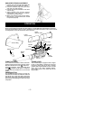
3. Closethezipper onthe bag.Makesurethe
zipper is closed completely.
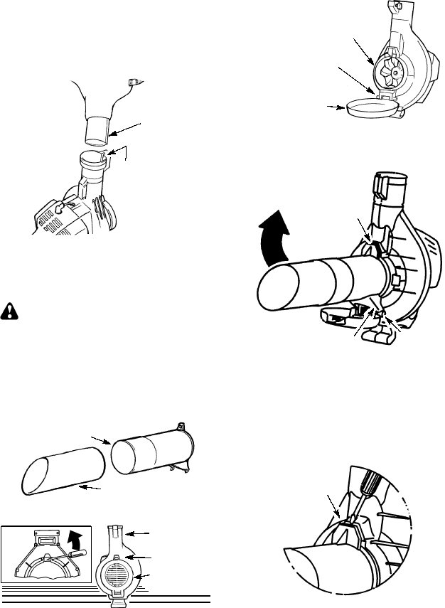
4. Remove bl ower tube from engine.
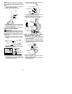
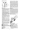
Rib
Groove
5. Insert theelbow tube intothe blower outlet.
Make sure elbow tube rib is aligned with
the blower outlet groove.
6. Turnknob clockwise tosecure elbowtube.
VACUUM TUBE ASSEMBLY
WARNING:
Stop engine and be sure
the impeller blades have stopped turning be-
fore opening the vacuum inlet door or at-
tempting to insert or remove the v acuum or
blower tubes. The rotating blades can cause
serious injury.
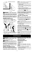
1. Align the lower vacuum tube as shown.
Push lower vacuum tube into upper vacu-
um tube.
Lower Vacuum Tube
Upper Vacuum
Tube
2. Insert the tip of a screwdriver into the latch
area of the vacuum inlet.
Latch Area
Blower
Outlet
Vacuum
Inlet Cover
Latch
Area
3. Gently tilt the handle of the screwdriver to-
ward the back of the unit to r elease the
latch while pulling up on the vacuum inlet
cover with your other hand.
4. Hold the vacuum inlet cover open until up-
per vacuum tube is installed.
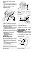
Vacuum Inlet
Vacuum
Inlet
Cover
Retaining Post
5. Place the hooks of theupper vacuum tube
on the r etaining posts of the unit.
6. Pivot the tube until it is secured to the
blower unit by the vacuum inlet latch.
Retaining
Post
Hook
Inlet Cover
Latch
PIVOT
HOW TO C ONVERT UNIT FROM
VACUUM USE TO BLOWER USE
1. Remove the vacuum tubes by inserting
the tip of a screwdriver into the latch area
of the vacuum inlet.
2. Gently tilt handle of screwdriver toward
the back of the unit to release the latch
while pulling up on the upper vacuum tube
with your other hand.
Latch Area
3. Remove the vacuum bag.
4. Close the vacuum inlet cover and make
sure it is latched closed.
5. Reinstall the blower tube (see BLOWER
TUBE ASSEMBLY).