


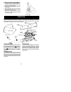
-- 3 --
plug disconnected. Keep vents and dis-
charge tubes free of debris which can ac-
cumulate and restrict proper air flow.
D
Never place any object in th e air inta ke
opening as this could re strict proper air flow
and cause damage to the unit.
D
Never use for spreading chemicals, fertil-
izers, orothersubstanceswhichmaycon-
tain toxic materials.
D
To avoid spreading fire, do not use near
leaf or brush fires, fireplaces, barbecue
pits, ashtrays, etc.
D
Use only for jobs explained in this manual.
MAINTAIN YOUR UNIT PROPERLY
D
Have all maintenance other than the rec-
ommended proceduresdescribed in thein-
struction manual performed by an autho-
rized service dealer.
D
Disconnect spark plug before performing
maintenance except for carburetor adjust-
men ts.
D
Use only recommended Poulan PRO
!
re-
placement parts; use of any other parts
may void your warranty andcause dam age
to your unit.
D
Empty fuel tank before storing th e un it. Use
up fu el leftincarburetor bystarting eng ine a nd
letting it run un til it stop s .
D
Do not use any accessory o r attachment
other than those recommended by manufac-
turer for use with your unit.
D
Do not store the unit o rfuel in a closed area
where fuel vapors can reach sparks or an
open flame from hot wa ter heaters,electric
motors or switches, furnaces, etc.
D
Store in a dry area out of reach of children.
SPECIAL NOTICE:
Exposure to vibra-
tions through prolongeduse of gasoline pow-
ered hand tools could cause blood vessel or
nerve damage in the fingers, hands, and
joints of people prone to circulation disorders
or abnormal swelling. Prolonged use in cold
weatherhasbeenlinked t ob loodvessel dam-
age in otherwisehealthypeople. Ifsymptoms
occur such as numbness, pain, loss of
strength, change in skin color or texture, or
loss of feeling in the fingers, hands, or joints,
discontinue the use of this tool and seek
medical attention. An antivibration system
does not guarantee the avoidance of these
problems. Users who operate power tools on
a continual and regular basis must monitor
closely their physical conditionand thecondi-
tion of this tool.
SPECIALN OTICE:
For users on U.S. For-
est Land and in some states, including Cali-
fornia (Public Resources Codes 4442 and
4443),Idaho,Maine, Minnesota,NewJersey,
Oregon, and Washington: Certain internal
combustion engines operated on forest,
brush,and/orgrass coveredland in theabov e
areas are required to be equipped with a
spark arresting screen, maintained in effec-
tive working order, o rthe enginemust becon-
structed, equipped, and maintained for the
prevention o f fire. Check with yourstate orlo-
cal authorities for regulations pertaining to
these requirements. Failure to follow these
requirementsis aviolation ofthelaw. This unit
is not factory equipped with a spark arresting
screen; however, a spark arresting screen is
available as anoptional part.If aspark arrest-
ing screen is required in your area, contact
your authorized service dealer for t hecorrect
kit. The spark arrestingscreen, blowertubes,
and nozzles must be assembled to unit to be
in full compliance with regula tions.
ASSEMBLY
W ARNING:
Stop engine and be sure
the impeller blades have stopped turning be-
fore opening the vacuum inlet door or at-
tempting to insert or remove the vacuum or
blower tubes. The rotating blades can cause
serious injury . Always disconnect the spark
plug before performing maintenance or ac-
cessing movable parts.
W ARNING:
If you receive your unit
assembled, check each step to insure your
unit is properly assembled and all fasteners
are secure. Follow all safety information in
the manual and on the unit.
D
A standard screwdriver is required for as-
sembly.
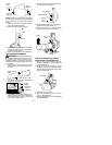
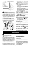
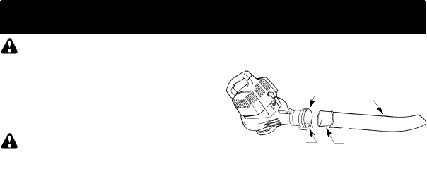
BLOWER TUBE ASSEMBLY
1. Align the rib on the blower tube with the
groove in the blower outlet; slide the tube
into place.
NOTE:
Knob m u stbe loose enoughtoallow
blower tube to be inserted in blower outlet.
Loosen knob by turning counterclockwise.
Blower
T ube
Blower
Outlet
Rib
Groove
2. Securethe tubeby turningthe knobclock-
wise.
3. To removethetube, tur ntheknobcounter-
clockwise to loosen the tube; remove the
tube.
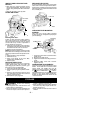
VACUUM BAG ASSEMBLY
1. Open the zipper on the vacuum bag and
insert the elbow tube.
2. Push the small end of the elbow tube
through the small opening in the bag.