


5
ASSEMBLY
W ARNING:
Stop the unit and dis-
connect from the power source before
opening the inlet cover or at tempting toin-
sert or remove the inlet restrictor , blower
tube, or vacuum tubes. The motor must
be stopped and the impeller blades no
longer turning to avoid ser ious injury from
the rotat ing blades.
W ARNING:
If received assembled,
ensur e y ou r unit is prope rly ass embled
and all fasteners are secure.
S
A standard screw driver is required f or
assembly.
BLOWER ASSEMBLY
NOTE:
Assembly instr uctio ns for using
your unit as a vacuum f ollow this section.
Attaching the blower tube
Ifyou have already assembled yourunit
foruse as a vacuum, referto the section
HOW TO CONVERT UNIT FROM VACUUM
USE TO BLOWER USE.
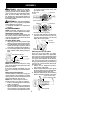
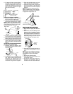
To attach blower tube:
1. Align the grooves on the blowertube
withthegroovesonthebloweroutlet.
2. Pushtheblowertubeontotheblower
outlet until it snaps into place (tube is
secured by red tube release button).
3. To remove the blower tube, press the
tube release button whi le pulling on
tube.
Blower Tube
Blower outlet
T ube Release Button
VACUUM ASSEMBLY
NOTE:
Assembly instructions for using
yourunitas ablowerareexplained inthe
previous section.
If you have already assembled your unit
for use as a blower , remove t he blower
tube.
Remove the inlet restrictor
An inlet r estrictor is used when using your
unit as a blower .This r estrictor is not used
during vacuum use andmust be r emoved
during assembly for vacuum use.
NOTE:
Be sure to keep the inlet re-
strictor for using your unit as a blower.
1. Ensure unit is stopped and extension
cord is unplugged.
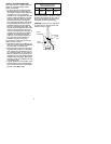
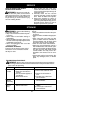
2. Open the inlet cover by inserting the
tipofa screwdriverintothe latcharea
on the blower unit. Gently tilt handle
of screwdrivertoward the frontof the
unit to release the latch while pulling
up on the vacuum inlet cover with
your other hand.
Vacuum Inlet Cover (closed)
Latch Area
Bottom view
of unit
Latch Area
Impeller
Vacuum Inlet Cover (opened)
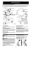
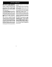
3. Turn the inlet restrictor counterclock-
wise and remove it from the unit. Do
not close the inlet door . You w ill next
attach the vacuum tubes.
Inlet
Restrictor
Vacuum
Inlet Cover
Attaching the vacuum tubes
There are 2 vacuum tubes, an upper
tube and a lower tube. The upper tube
has a vacuum assist handle attached to
oneendand iscut straighton bothends.
The upper tube attaches to the blower
unit. The lower tube has an angled end
that you point toward the ground during
vacuum use.The lowertube attaches to
the upper tube.
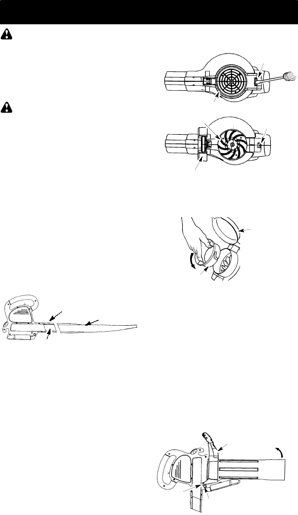
1. Ensure unit is stopped and exten-
sion cord is unplugged.
2. While holding inlet cover open, place
the hooks o f thevacuum assist handle
on the retaining posts of the unit.
3. Raise the tube until it is secured to t he
blower unit by the r ed inlet cover latch.
Retaining Post
Vacuum Assist Handle
Upper V acuum Tube
Hook