


14
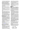
AIR FILTER
CAUTION:
Do not c lean filter in gasoline
or other flammable solvent to avoid creating
a fire hazard or producing harmful evapora-
tive emissions.
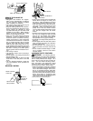
Cleaning the air filter:
A dirty air filter decreases engine perform-
ance and increases fuel consumption and
harmful emissions. Always clean after every
5 hours of operation.
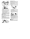
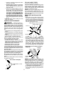
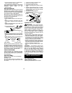
1. Loosen 3 screws on cylinder cover.
2. Remove cylinder cover.
3. Remove air filter.
4. Clean the air filter using hot soapy water.
Rinse with clean cool water. Air dry com-
pletely before reinstalling.
5. Lightly oil air filter before installing to im-
prove t he efficiency of air filter. Use
2 --cycle engine oil or motor oil (SAE 30).
Squeeze excess oil from f ilter.
6. Reinstall air filter.
7. Reinstall cylinder cover and 3 screws.
TIghten securely.
Air Filter
Cylinder
Cover
Screws
Cylinder
Cover
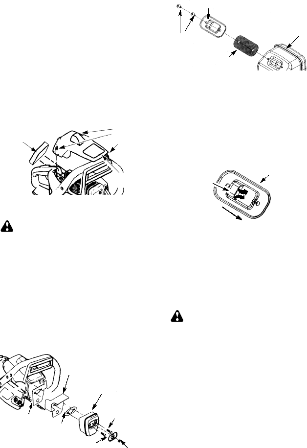
INSPECT MUFFLER AND SPARK
ARRESTING SCREEN
WARNING:
The muffler on this
product contains chemicals known to the
State of California to cause cancer.
As the unit is used, carbon deposits build up
on the muffler and spark arresting screen,
and must be removed to avoid creating afire
hazard or affecting engine performance.
Replace the spark arresting screen if breaks
occur.
CLEANING THE SPARK ARREST-
ING SCREEN
Cleaning is required every 25 hours of op-
eration o r annually, whichever comes first.
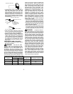
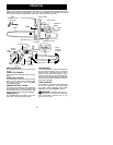
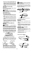
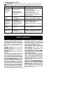
Muffler
Gasket
Muffler
Bolts
Muffler
Locknut
Outlet
Guide
Bolt Cover
Backplate
1. Loosen and remove the locknut from the
bolt cover.
2. Remove the bolt cover.
3. Loosen and remove the 2 muffler bolts.
Remove the muffler, muffler gasket, out-
let guide and backplate. Notice the ori-
entation of these parts for reassembling.
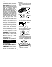
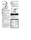
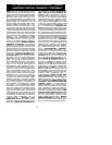
4. Locate the 2 outlet cover screws on t he
muffler. Loosen and remove both
screws.
5. Remove the outlet cover .
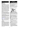
BACK VIEW OF
MUFFLER
Muffler
Spark Arresting
Screen
Outlet Cover
Screws
6. Remove spark arresting screen.
7. Clean the spark arresting screen with a
wirebrush. R eplacescreen if any w ir esare
broken or scr een is blocked after cleaning.
8. Reinstall spar k arresting scr een.
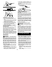
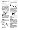
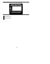
9. Reinstall outlet cover and 2 screws. En-
sure outlet cover and both screws are re-
installed correctly (see illustrations) to
prevent damage to the saw. The ex-
haust outlet must face the chain brake
(bar side) of the saw .
Exhaust Outlet must face chain
brake (bar s ide) of chain saw
Outlet Cover
Exhaust
Outlet
10. Inspect the muffler gasket and replace if
damaged.
11. Reinstall backplate, outlet guide, muffler
gasket, and muffler using muffler bolts.
Tighten until secure.
12. Reinstall bolt cover and locknut. Tighten
securely.
CARBURETOR ADJUSTMENT
WARNING:
The chain will be mov-
ing during most of this procedure. Wear your
protective equipment and observe all safety
precautions. The chain must not move at idle
speed.
The carburetor has been carefully set at the
factory. Adjustments may be necessary if
you notice any of the f ollowing conditions:
S
Chain moves at idle. See IDLE SPEED--T
adjusting procedure.
S
Saw will not idle. See IDLE SPEED--T ad-
justing procedure.
Idle Speed--T
Allow engine to idle. If the chain moves, idle
is too fast. Ifthe engine stalls, idle is too slow.
Adjust speed until engine runs without chain
movement (idle too fast) or stalling (idle too
slow). The idle speed screw is located in the
area above the primer bulb and is labeled T.
S
Turn idle speed screw (T) clockwise to in-
crease engine speed.