


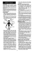

SAFETY NOTICE: Exposure to vibrations
through prolonged use of gasoline
powered hand tools could cause blood
vessel or nerve damage in the fingers,
hands, and joints of people prone to
circulation disorders or abnormal swellings.
Prolonged use in cold weather has been
linked to blood vessel damage in otherwise
healthy people. If symptoms occur such as
numbness, pam, loss of strength, change in
skin color or texture, or loss of feeling inthe
fingers, hands, or joints, discontinue the
use of this tool and seek medical attention.
An anti-vibration system does not
guarantee the avoidance of these
problems. Users who operate power tools
on a continual and regular basis must
monitor closely their physical condition and
the condition of this tool.
SPECIAL NOTICE: Your saw is
equipped with a temperature limiting
muffler and spark arresting screen which
meets the requirements of California Codes
4442 and 4443. All U.S. forest land and the
states of California, Idaho, Maine,
Minnesota, New Jersey, Oregon, and
Washington require many internal
combustion engines to be equipped with a
spark arrestor screen by law. If you operate
a chain saw in a state or locale where such
regulations exist, you are legally
responsible for maintaining the operating
condition of these parts. Failure to do so is
a violation of the law. Refer to the SERVICE
section for maintenance of the Spark
Arrestor.
Failure to follow all Safety Rules and Precau-
tions can result inserious injury. Ifsituations
occur which are not covered inthis manual,
use care and good udgement. If you need
assistance, contact your retailer or call
1-800-554-6723.
The assembly tool provided with your saw is
the only tool needed for assembly. Protec-
tive gloves (not provided) should be worn
during assembly.
ATTACHING THE BAR & CHAIN (if not
already attached)
WARNING: Recheck each assembly
step if the saw is received assembled. Al-
ways wear gloves when handling the chain.
The chain is sharp and can cut you even
when it is not moving!
• Loosen and remove the clamp nuts and
the bar clamp from the saw.
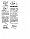
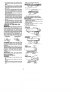
• Remove the plastic shipping spacer (if
present).
Location of shipping spacer
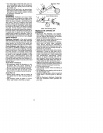
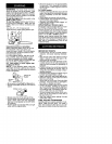
• An adjusting pin and screw are used to
ad ust the tension of the chain. It is very
mportant when assembl ng the bar that
the pin located on the adjusting screw
aligns with a hole in the bar. Turning the
screw will move the ad ustment pm up
and down the screw. Locate th s adjust-
ment pin before you begin mounting the
bar onto the saw. See illustration below.
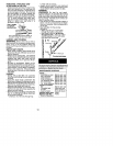
view of
Inside
_1_r Clamp
Adjustment screw
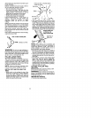
• Turn the adjusting screw counterclock-
wise to move the adjusting pin almost as
far as it will go to the rear. This should al-
low the pin to be near the correct position.
Further adjustment may be necessary as
you mount the bar.
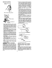
• Mount the bar as illustrated.
• Slide the bar toward the rear of the saw as
far as possible.
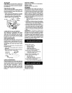
• Prepare the chain by checking the proper
direction. Without following the illustration
it is easy to place the chain on the saw the
wrong direction. Use the illustration of the
chain to determine the proper direction.
• Place the chain onto the sprocket located
behind the clutch drum. Fit the chain be-
tween the teeth in the sprocket.
• Start at the top of the bar and fit chain into
groove around the guide bar.
• Pull the bar forward until the chain is snug
in the groove of the bar.
• Hold guide bar against the saw frame and
install bar clamp. Make sure the adjusting
pin is aligned with the hole in the bar. Re-
member this pin moves the bar forward
and backward as the screw is turned.
• Replace the bar clamp nuts and tighten
finger tight. Once the chain is tensioned
you will need to tighten bar clamp nuts.
5