


5
S
Squeeze and hold the throttle trigger. Keep
throttle trigger fully squeezed until the en-
gine runs smoothly.
S
Pull starter rope sharply until engine runs,
but no more than 5 pulls.
S
Allow engine to r un 15 seconds, t hen move
the choke lever to the O FF CHOKE position.
NOTE:
If engine has not started, pull starter
rope 5 more pulls. If engine still does not run, it
is probably flooded.
STARTING A FLOODED ENGINE
Flooded engines can be started by placing
the choke lever in the OFF CHOKE position;
then, pul l the rope to clear the engine of ex-
cess fuel. This could require pulling the starter
handle many times depending on how badly
the unit is flooded.
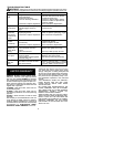
If the unit still doesn’t start, refer to
TROUBLESHOOTING TABLE or call
1-800-554--6723.
USING YOUR UNIT
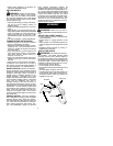
OPERATING POSITION
Eye
Protection
Long Pants
Heavy Shoes
ALWAYS WEAR:
Cut from your left to your right.
TRIMMER LINE ADVANCE
Advance line by tapping the bottom of the cut-
ting head lightly on the ground while engine is
running at full speed. The metal line limiter
blade attached to the shield will cut the line to
the proper length.
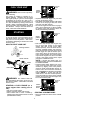
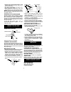
REPLACING THE LINE
S
Remov e spool by firmly pulling on tap button.
S
Clean entire surface of hub and spool.
S
Replace with a pre-wound spool, or cut two
lengths of
12-1/2
feet of 0.080” (2 mm) di-
ameter Poulan PRO
!
brand line. Never
use wire, rope, string, etc., which can break
off and become a dangerous missile.
S
Insert ends of the line about 1/2 inch (1 cm)
into the small hole on the inside of spool.
Small
Holes
Spool
Hub
Line in Notch
Line in Notch
Line exit holes
S
Wind the line evenly and tightly onto the
spool. Wind in t he direction of the arrows
found on the spool.
S
Push the lines into the notches, leaving 3 to
5 inches (7 -- 12 cm) unwound.
S
Insert the lines into the the exit holes in the
hub as shown in the illustration.
S
Align the notches with the line exit holes.
S
Push spool into hub until it snaps into place.
S
Pull the lines extending outside of the hub to
release them from the notches.
REPLACING THE CUTTING HEAD
S
Push in locking lever and hold.
S
Rotate dust cup until the locking lever falls
into one of the grooves
.
Locking Lever
S
Continue to hold in locking lever. This will pre-
vent the shaft from turning while removing
and installing trimmer head.
S
Remove trimmer head by turning clockwise.
S
Thread r eplacement tr immer head onto the
shaft by turning counterclockwise. Tighten
until secure.
S
Release locking lever.
SERVICE
We r ecommend all service and adjustments not
listed in this manual be performed by an
authorized service dealer.
CARBURETOR ADJUSTMENTS
Your carburetor is equipped with limiter caps.
Carbur etor adjustments is a complicated task.
We recommend that you take your unit to an au-
thorized ser vice deal er. Damage will occur i f you
turn the needles beyond the limiter stops.
IGNITION TIMING
The ignition timing is fixed, non--adjustable.
SPARK PLUG
Replace the spark plug yearly using a Cham-
pion RCJ--8Y plug. Spark plug gap is 0.025”.
NEED ASSISTANCE?
Need Assistance?
Call 1--800--554--6723
Need Service Part?
Contact your dealer.