


20
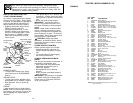
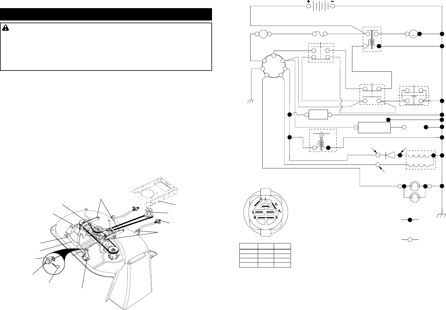
SERVICE AND ADJUSTMENTS
CAUTION: Before performing any service or adjustments:
• Depress clutch/brake pedal fully and set parking brake.
• Place gearshift lever in neutral (N) position.
• Place attachment clutch in “DISENGAGED” position.
• Turn ignition key “OFF” and remove key.
• Make sure the blades and all moving parts have completely stopped.
• Disconnect spark plug wire from spark plug and place wire where it cannot
come in contact with plug.
TRACTOR
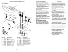
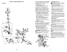
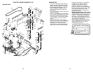
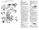
TO REMOVE MOWER
Mower will be easier to remove from the
right side of tractor.
• Place attachment clutch in “DISEN-
GAGED” position.
• Move attachment lift lever forward to
lower mower to its lowest position.
• Roll belt off engine pulley.
• Remove small retainer spring, and lift
clutch spring off pulley bolt.
• Remove large retainer spring, slide
collar off and push housing guide out of
bracket.
• Disconnect anti-swaybar from chassis
bracket by removing retainer spring.
• Disconnect suspension arms from rear
deck brackets by removing retainer
springs.
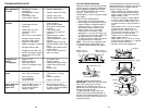
CLEANING
• Clean engine, battery, seat, finish, etc.
of all foreign matter.
• Keep finished surfaces and wheels free
of all gasoline, oil, etc.
• Protect painted surfaces with automo-
tive type wax.
We do not recommend using a garden
hose to clean your tractor unless the
electrical system, muffler, air filter and
carburetor are covered to keep water out.
Water in engine can result in a short-
ened engine life.
• Disconnect front links from deck by
removing retainer springs.
• Raise lift lever to raise suspension
arms. Slide mower out from under
tractor.
IMPORTANT: If an attachment other than
the mower deck is to be mounted on the
tractor, remove the front links and hook
the clutch spring Into square hole in
frame.
TO INSTALL MOWER
• Raise attachment lift lever to its highest
position.
• Slide mower under tractor with dis-
charge guard to right side of tractor.
• Lower lift lever to its lowest position.
• Install mower in reverse order of
removal instructions.
3
8
38
4
2
42
Suspension Arms
Retainer Springs
(Both Sides)
Retainer Spring
Anti-Sway Bar
Housing Guide
Front Link
Collar
Engine Pulley
Large Retainer Spring
Clutch Spring
Small Retainer Spring
Bracket
Square Hole
29
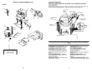
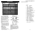
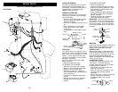
TRACTOR -- MODEL NUMBER 271470
SCHEMATIC
BATTERY
FUSE
IGNITION
SWITCH
RED
RED
RED
BLACK
IGNITION
UNIT
HEADLIGHTS
REMOVABLE
CONNECTIONS
BLACK
BLACK
BLACK
WHITE
WHITE
WHITE
RED
BLACK
ORANGE
BLACK
BROWN
BLACK
BLACK
BLACK
STARTER
M
SEAT SWITCH
(NOT OCCUPIED)
GROUNDING
CONNECTOR
ATT'MENT CLUTCH
(CLUTCH OFF)
CLUTCH / BRAKE
(PEDAL UP)
SOLENOID
BLACK
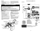
LIGHTING SYSTEM OUTPUT
5 AMP AC @ 3600 RPM
ALTERNATOR
14 VOLTS AC MIN. @ 3600 RPM (LIGHTS OFF)
DIODE
28 VOLTS AC MIN. @ 3600 RPM
(CHARGING SYSTEM DISCONNECTED)
CHARGING SYSTEM OUTPUT
3 AMP DC @ 3600 RPM
NOTE
YOUR TRACTOR IS
EQUIPPED WITH A SPECIAL
ALTERNATOR SYSTEM.
THE LIGHTS ARE NOT
CONNECTED TO THE
BATTERY, BUT HAVE THEIR
OWN ELECTRICAL SOURCE.
BECAUSE OF THIS, THE
BRIGHTNESS OF THE LIGHTS
WILL CHANGE WITH ENGINE
SPEED. AT IDLE THE LIGHTS
WILL DIM. AS THE ENGINE IS
SPEEDED UP, THE LIGHTS
WILL BECOME THEIR BRIGHTEST.
WIRING INSULATED CLIPS
NOTE: IF WIRING INSULATED CLIPS WERE REMOVED FOR
SERVICING OF UNIT, THEY SHOULD BE REPLACED TO
PROPERLY SECURE YOUR WIRING.
A
AMMETER
RED
G
B
S
M
A1
A2
L
HOUR
METER
(OPTIONAL)
(OPTIONAL)
SPARK
PLUG
GAP
(2 PLUGS ON
TWIN CYL. ENGINES)
IGNITION SWITCH
CIRCUITPOSITION
OFF
B+A1RUN/LIGHT
B + S + A1START
M+G+A1
B+A1RUN
“MAKE”
A2+L
NONE
NONE
NONE
(IF SO EQUIPPED)
NON-REMOVABLE
CONNECTIONS
BLUE
FUEL SHUT-OFF SOLENOID
FUEL
LINE