


24
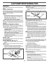
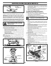
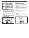
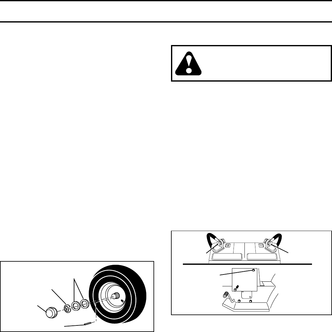
TO REMOVE WHEEL FOR REPAIRS
(See Fig. 28)
• Block up axle securely.
• Remove axle cover, retaining ring and washers to allow
wheel removal (rear wheel contains a square key - Do
not lose).
• Repair tire and reassemble.
• On rear wheels only: align grooves in rear wheel hub
and axle. Insert square key.
• Replace washers and snap retaining ring securely in
axle groove.
• Replace axle cover.
NOTE: To seal tire punctures and prevent flat tires due to
slow leaks, tire sealant may be purchased from your local
parts dealer. Tire sealant also prevents tire dry rot and
corrosion.
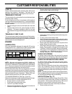
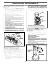
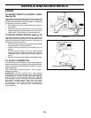
TO START ENGINE WITH A WEAK BATTERY
(See Fig. 29)
CAUTION: Lead-acid batteries generate
explosive gases. Keep sparks, flame and
smoking materials away from batteries.
Always wear eye protection when around
batteries.
If your battery is too weak to start the engine, it should be
recharged. (See "BATTERY" in the CUSTOMER RESPON-
SIBILITIES section of this manual).
If “jumper cables” are used for emergency starting, follow this
procedure:
IMPORTANT: YOUR TRACTOR IS EQUIPPED WITH A 12
VOLT NEGATIVE GROUNDED SYSTEM. THE OTHER
VEHICLE MUST ALSO BE A 12 VOLT NEGATIVE
GROUNDED SYSTEM. DO NOT USE YOUR TRACTOR
BATTERY TO START OTHER VEHICLES.
TO ATTACH JUMPER CABLES -
• Connect each end of the RED cable to the POSITIVE (+)
terminal of each battery, taking care not to short against
chassis.
• Connect one end of the BLACK cable to the NEGATIVE
(-) terminal of fully charged battery.
• Connect the other end of the BLACK cable to good
CHASSIS GROUND, away from fuel tank and battery.
TO REMOVE CABLES, REVERSE ORDER -
• BLACK cable first from chassis and then from the fully
charged battery.
• RED cable last from both batteries.
RETAINING
RING
WASHERS
AXLE
COVER
SQUARE KEY
(REAR WHEEL ONLY)
FIG. 28
TRANSMISSION REMOVAL/REPLACEMENT
Should your transmission require removal for service or
replacement, it should be purged after reinstallation and
before operating the tractor. See “PURGE TRANSMIS-
SION” in the Operation section of this manual.
SERVICE AND ADJUSTMENTS
FIG. 29
“POSITIVE”
(+)
“NEGATIVE”
(-)
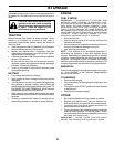
L.H. PANEL
BOLT
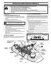
TO ADJUST STEERING WHEEL ALIGNMENT
If steering wheel crossbars are not horizontal (left to right)
when wheels are positioned straight forward, remove steer-
ing wheel and reassemble per instructions in the Assembly
section of this manual.
FRONT WHEEL TOE-IN/CAMBER
The front wheel toe-in and camber are not adjustable on
your tractor. If damage has occurred to affect the front
wheel toe-in or camber, contact your nearest authorized
service center/department.