


22
SERVICE AND ADJUSTMENTS
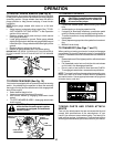
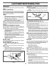
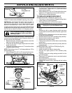
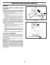
MANDREL
FIG. 22
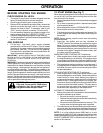
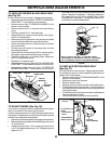
FIG. 23
TO REPLACE MOWER DRIVE BELT
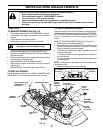
MOWER DRIVE BELT REMOVAL (See Fig. 24)
• Park tractor on a level surface. Engage parking brake.
• Lower mower to its lowest position.
• Disengage belt tention rod from lock bracket.
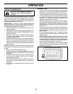
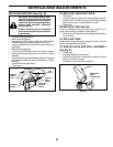
FIG. 24
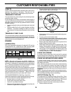
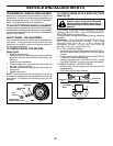
FIG. 21
LIFT LINK
ADJUSTMENT NUT
SUSPENSION ARM
BOTH FRONT LINKS MUST BE EQUAL IN LENGTH
TRUNNION
FRONT
PLATE
ASSEMBLY
NUT “C”
NUT “D”
• Remove screws from R.H. mandrel cover and remove
cover.
• Remove any dirt or grass clippings which may have
accumulated around mandrels and entire upper deck
surface.
• Disconnect R.H. suspension arm from rear deck bracket
by removing retainer spring.
• Roll belt over the top of R.H. mandrel pulley carefully.
• Remove belt from electric clutch pulley.
• Remove belt from idler pulleys.
• Check primary idler arm and two idlers to see that they
rotate freely.
• Be sure spring is securely hooked to primary idler arm
and spring arm.
MOWER DRIVE BELT INSTALLATION (See Fig. 24)
• Install belt in both idlers.
• Install new belt onto electric clutch pulley.
• Roll belt into upper groove of R.H. mandrel pulley
carefully.
• Carefully check belt routing making sure belt is in the
grooves correctly.
• Reconnect R.H. suspension arm to rear deck bracket
with retainer spring.
• Reassemble R.H. mandrel cover.
• Engage belt tension rod by pushing rod into locking
bracket.
CAUTION: Rod is spring loaded. Have a
tight grip on rod and release slowly.
PRIMARY
IDLER ARM
R.H.
MANDREL
IDLER
PULLEY
ELECTRIC
CLUTCH
PULLEY
SPRING
ARM
BELT
TENSION ROD
(DISENGAGED
POSITION)
RH MANDREL
COVER
RH
SUSPENSION
ARM
IDLER
PULLEY
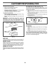
FRONT-TO-BACK ADJUSTMENT (See Figs. 22 and 23)
IMPORTANT: DECK MUST BE LEVEL SIDE-TO-SIDE. IF
THE FOLLOWING FRONT-TO-BACK ADJUSTMENT IS
NECESSARY, BE SURE TO ADJUST BOTH FRONT LINKS
EQUALLY SO MOWER WILL STAY LEVEL SIDE-TO-SIDE.
To obtain the best cutting results, the mower blades should
be adjusted so the front tip is approximately 1/8" to 1/2" lower
than the rear tip when the mower is in its highest position.
CAUTION: Blades are sharp. Protect your
hands with gloves and/or wrap blade
with heavy cloth.
Check adjustment on right side of tractor. Position any blade
so the tip is pointing straight forward. Measure distance "B"
at front and rear tip of the blade.
• Before making any necessary adjustments, check that
both front links are equal in length.
• If links are not equal in length, adjust one link to same
length as other link.
• To lower front of blade, loosen nut “C” on both front links
an equal number of turns.
NOTE: Each full turn of nut “C” will change distance. “B” by
approximately 3/16".
• When distance “B” is 1/8" to 1/2" lower at front than rear,
tighten nut “D” against trunnion on both front links.
• To raise front of blade, loosen nut “D” from trunnion on
both front links. Tighten nut “C” on both front links an
equal number of turns.
• When distance “B” is 1/8" to 1/2" lower at front than rear,
tighten nut “D” against trunnion on both front links.
• Recheck side-to-side adjustment.
“B”
“B”