


Part 3
V. HARDWARE INSTALLATION
A. VGA Port Power Preparation
1. Inquire for technical support from your dealer to set the power support in
the VGA port of the FT system following the relevant Technical Manual
of the FT system. Please note that once the VGA port is no longer to be
occupied by the LM-6601, this power support must be discontinued!
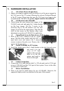
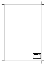
B. Fix Bracket onto LM-6601
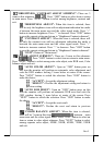
2. Unfold down the semi-circular base tongue of the
LM-6601 main unit and apply the L shape bracket
on this base tongue. Use the 2 screws in the
accessory bag to fix the bracket over the base
tongue as circled in the right picture. Note that the
slots for the screws on the bracket allow some
adjustment on position of LM-6601 for application.
C. Open Back Cover & Pole Cover of FT System
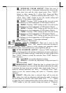
3. Refer to the User’s Manual of the FT system
about “INSTALLING BASE MOUNT KIT” to
open back cover and remove the 2 arrowed
screws to remove the pole cover. Preserve the 2
screws for the next step.
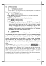
D. Install LM-6601 to FT System
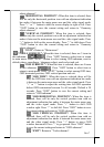
4. Install the slender part of the L shape bracket to the hole for pole cover
and screw it to top
cover of FT base
tightly at the arrowed
holes as in the left
picture and result is
shown at the right.
E. Cable Connection
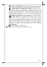
5. Connect the VGA cable that has both 3 x 5 D sub male ends to VGA port
at rear of LM-6601 and the VGA port of host system. Screw in the cable
to connectors at both ends.
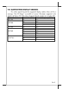
F. Driver Installation
6. There is no need to install driver for use of LM-6601. However, the
supported display modes are tabulated at last part of this manual